


Written by Elecia White.
In Part 1, I started to take apart by BB8 droid. In Part 2, I took a close look at the hardware. Now, let’s see what I can discover about the software. Remember, I don't work for Sphero and I don’t usually take apart my toys so reverse engineering is new to me. But it is really, really fun.
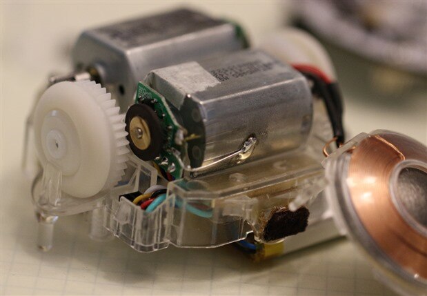
I didn't expect for this to be such a great tool to explain some interesting embedded software concepts. But before we get to that, let’s look at the board. There are two through-hole connectors that go to the motor assemblies, one for the right motor, one for the left.
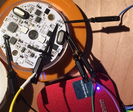
The motor is controlled by the main processor (STM32F373). It sends PWM (pulse-width modulation) signals to the Toshiba TB6552FNG which magnifies the puny 3.3V signals (and only a little bit of current sourced by the processor) to signals that are the 7 or 8V of the battery and much higher current. I’m not going to worry about the signals between the two chips; you can read the datasheet for that. Instead, I am going to focus on the signals being sent to that motor which means hooking onto those pins with my Saleae oscilloscope. I chose to focus on the right motor though they seemed about the same.
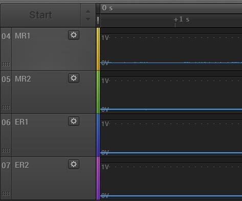
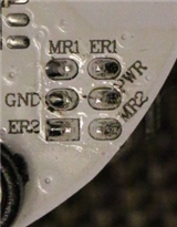
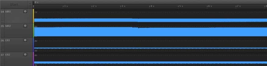
The signals are MR1 (yellow), MR2 (green). These go from the Toshiba chip and drive the motor. ER1 (blue) and ER2 (violet) go to the main processor and provide feedback from the motor. Here they are when the motors are off (boring!).
As soon as the app is connected, the motors go from free moving to held in place (BB8 wants to be upright at all times and holds its position).
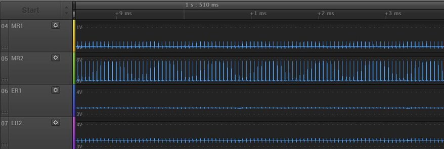
The signal capture is still straight lines, mostly. MR1 is a noisy zero. MR2 goes from 0 to 8V (the Vbat of a mostly full pair of batteries). ER1 and ER2 are at 3.3V with a bit of noise.
Zooming in, you can see that MR2 is mostly zero as well.
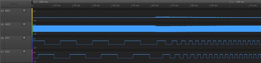
The motor here is being energized just a bit to make sure the wheels can's spin freely. Holding still is only a little interesting. Moving is where things get good. In the following 10s trace, the system is initially sleeping. I connected it so that BB8 would wake up and made some adjustments to be upright. Then, at around 3.5s, I pushed the button to make BB8 nod its head.
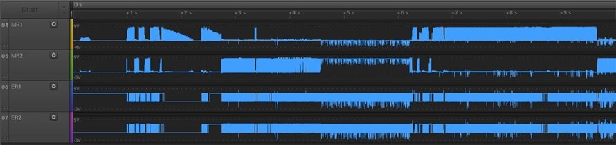
After the nod, the system noted that the motors were not having the desired effect on the inertial sensor. Since the motors are not encased in its spherical shell, they don’t move the system as the firmware expects. This causes the firmware to become quite unhappy, driving the motors ever faster, full blast one way then the other. Essentially, the phone app directs the motion of the device, the firmware tried to implement the app’s command. Since my device’s motion is impaired, the firmware tries everything.
Sensing the Motor Position
But while that was all very exciting, it is the nod that is interesting from a motor drive perspective. Zooming in around the 3s mark, you can see the motor turning one direction, slowing down, briefly turning the other direction and increasing speed.
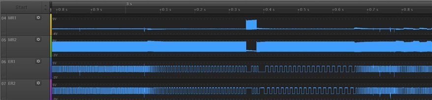
From this it looks like MR1 is motor drive in one direction, the MR2 is the other direction. These are PWM driven (more on that in a minute). The ER1 and ER2 are quadrature encoded feedback, describing the speed of the shaft turning. Let me explain that that means.
You can see how the motor drive affects the speed as the motor speeds up (near ~3.6s). Looking more closely, you can see how the encoder toggles speed up.
The two encoder lines indicate both direction (which one is in front) and speed (how fast they toggle). The speed is easy to imagine: if you were driving along a road where all the houses looked the same: house and yard, house and yard, (up and down), as far as the eye can see. As you zoom along, the houses go by faster. If you go slowly, the houses go by more slowly.
Now for direction: imagine the houses on the other side of the street are offset by a quarter of a house. The houses part overlaps a little, the yard part overlaps. Ok, this analogy has gotten to be worse than looking at the signal itself. See how ER1 has a rising edge before ER2? If the motor was spinning the opposite direction, ER2 would lead ER1. Since they are on a motor turning around in a circle (instead of house in a linear row), we say they are off by 90 degrees, one quarter of a circle.
These two signals go into the main processor, into pins that can function as timer/counter inputs. These can be put into encoder interface mode which will do the counting for you. (See Figure 88, taken from the STM32F37xx Reference Manual.)
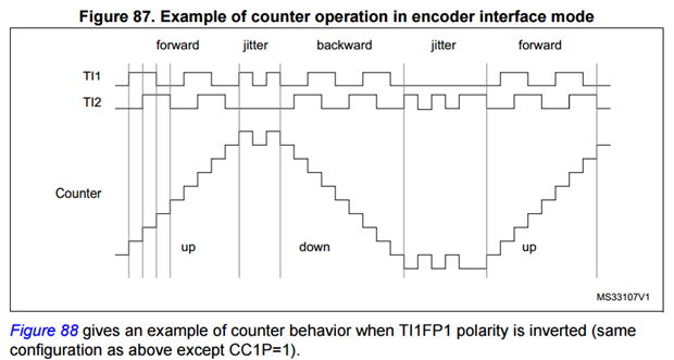
While the ER1 and ER2 signals move around a lot, you get a counter output. (Note: this is also true for the left side motor with the EL1 and EL2 signals.) The counter does not tell you where you are in the motor rotation as the encoder wheel doesn’t indicate absolute position: it only knows about relative position.
Many systems solve this by having a home position. On initialization, you can move the motor slowly until you find the home position, usually with a different sensor. Then you can use the quadrature encoder to counter method to say where you are precisely.
BB8 does not need to know its motors’ precise location, only that they are moving as commanded (and given the way it freaks out when it thinks the motors aren’t moving, I’m not sure they are checking the position all that closely).
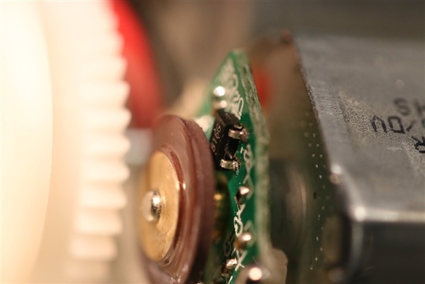
As the black disk turns, the embedded magnetic information is shown to each of the Hall effect sensors which output the signal they are seeing (the ER1 and ER2 signal, one for each sensor). Those get fed into the processor which reads the state of the sensors, providing the software with a (relative) position count, direction, and speed. However, if your processor can’t do the counting for you, using Hall effect sensors as motor encoders will still work with a little software finesse.
Driving the motor
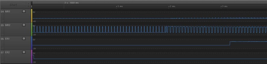
The processor outputs a digital signal, not an analog one. The signal is a series of pulses whose widths are proportional to the amount of oomph the motor has to drive the signal. The more time the signal is high, the faster the motor goes. It switches back and forth so fast that the DC motor doesn’t know that the signal is digital, it treats it as an analog cycle at the average level. This is called PWM or pulse width modulation. (It is handy for dimming LEDs as well as motors.)
For BB8, the pulses repeat at around 17,000 times per second (17kHz). At the beginning of the trace, it is only about 10% on (high). At the end, it is closer to on 75% of the time. I wrote about PWM in my book (Making Embedded Systems).
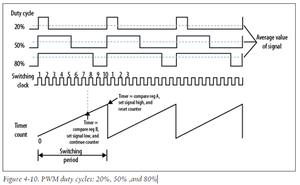
We can’t know the switching period of BB8 without looking in the code. But we can see the duty cycle on the motor drive signals and we can see how that changes the speed of the motors on the encoder feedback.
For additional information and to try this all out yourself, see this Hall Effect sensor kit and explanation: https://www.pololu.com/product/2598.
