


R-2R sounds like it might be a robot from the Star Wars universe (a ladder robot, maybe?),
but in electronics it's the name of a resistor network that can be used to make a DAC
(digital-to-analogue converter). I'm going to try doing just that with an Arduino and see
how I get on. If this works, it's then going to be the basis for a piece of Arduino test
equipment controlled by the SCPI library that Jan introduced us to last weekend.
The network looks like this. This is from the simulator and shows the results of the DC
analysis (the MOSFETs in the processor are replaced with switches - I did that just to get
a feel for what it was doing - the switch settings here are for an output of 0x40).

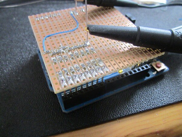
I built it on a piece of tri-pad board (it's like stripboard, but the strips are cut every
3 holes). I used 4.7k 0805 surface-mount resistors. They were 1% resistors, but they came
from the same reel and matched each other better than that (I made the 2R resistors from
two in series so that the close matching would apply between the R and 2R ones as well).
Here's a photo of the board plugged into a Uno.
The initial sketch I used is very simple. It just increments a value that gets written to
the output port and produces a ramp from 0V to 5V. [This DAC doesn't have a reference;
instead it's ratiometric and gives us a proportion of the supply voltage. That can be a
good thing or a bad thing, depending on what we want to do with it.]
/* AD Test
 */
unsigned char outputValue = 0;             // output value
const long interval = 4;           // interval at which to step (milliseconds)
void setup() {
  // set the digital pin as output:
  pinMode(0, OUTPUT);
  pinMode(1, OUTPUT);
  pinMode(2, OUTPUT);
  pinMode(3, OUTPUT);
  pinMode(4, OUTPUT);
  pinMode(5, OUTPUT);
  pinMode(6, OUTPUT);
  pinMode(7, OUTPUT);
}
void loop() {
    outputValue = outputValue + 1;
    PORTD = outputValue;
}
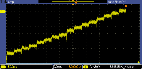
Here it is on the scope. The only load here is the input impedance of the x10 probe (10M
and about 12pF). We'll come back to the issue of the load in a moment.
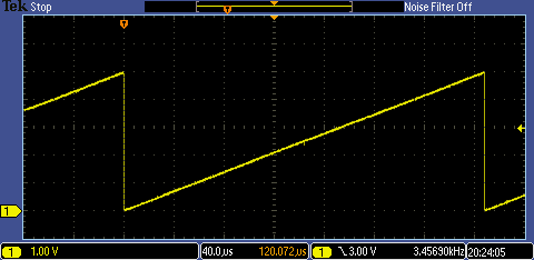
It's looking promising - that's quite a reasonable ramp.
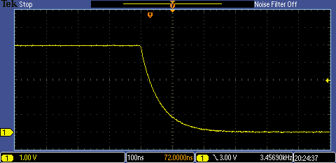
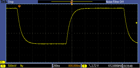
Next is the fall from 5V to 0V at the end of the ramp. It's almost a pure CR
characteristic, with the resistance from the ladder and the capacitance from the probe:
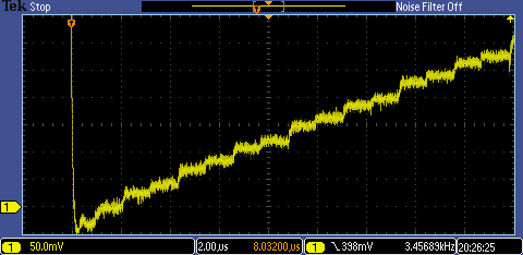
This next one shows the steps at the bottom end. They are a bit uneven, but it's not bad
for 1% resistors.
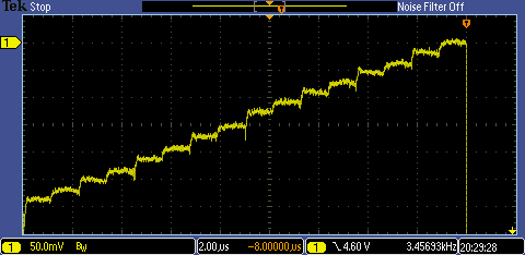
Here's the top end (there's a 5V offset on the trace, so the marker is at 5V, not 0V):
and here it is again with the scope's 20MHz bandwidth filter on:
I then adapted the sketch to step up and down between 0x40 and 0xBF. That's a quarter to
threequarters of fullscale, with every bit in the word changing. The incrementing variable
that you can see in the sketch is just to waste a little time and roughly balance the time
spent doing the loop (I had to mark it as being volatile to stop the compiler 'helpfully'
removing it). That looks good. It's a bit better than you could do by filtering
PWM - it settles in about 500nS!
/* AD Test
 */
volatile unsigned char outputValue = 0;             // output value
const long interval = 4;           // interval at which to step (milliseconds)
void setup() {
  // set the digital pin as output:
  pinMode(0, OUTPUT);
  pinMode(1, OUTPUT);
  pinMode(2, OUTPUT);
  pinMode(3, OUTPUT);
  pinMode(4, OUTPUT);
  pinMode(5, OUTPUT);
  pinMode(6, OUTPUT);
  pinMode(7, OUTPUT);
}
void loop() {
    PORTD = 0x40;
    outputValue = outputValue + 1;
    outputValue = outputValue + 1;
    PORTD = 0xBF;
}
BTW my choice of 4.7k was a bit arbitrary. I didn't want to go too low, where the 20R
resistance of the MOSFETs in the output drivers would start to become significant, and I
didn't want to go too high where it would become even more noisy and the slewing rate
would reduce further. It probably wouldn't hurt being a bit lower than this, but since
I've built it now and it looks quite useable I'm going to move to the next step rather
than rework it.
The output resistance is too high for it to be able to drive anything other that a high impedance
input without seriously affecting the output accuracy, so it needs a buffer on the output;
I'll do that with an op-amp. I'll also try controlling it with the SCPI library and taking
some measurements to get a feel for the accuracy. That will be part two.
Part one: Arduino: R-2R Experiment
Part two: Arduino: R-2R: Sine On You Crazy Diamond
Part three: Arduino: R-2R: Buffer, Attenuate, and Filter
Part four: Arduino: R-2R: "We Interrupt This Programme..."
Part five: Arduino: R-2R: "Resistance is..."?
Part six: Arduino: R-2R: Setting the Output Frequency
Part seven: Arduino: R-2R; "A Sweep is as Lucky, as Lucky Can Be..."
Part eight: Arduino: R-2R: Setting the Signal Amplitude
Top Comments