


Arduino Tutorial #6: Introduction To Arduino Using Matlab Simulink
In this tutorial, I would like to introduce you to the Arduino using the Matlab Simulink. Previously we have seen how to program an Arduino using the IDE. The process is pretty much the same, but the methods are different. The first thing you need to to do is to install the Matlab.

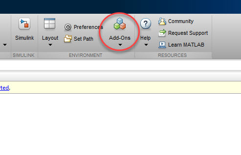
The installation process is straightforward. Once you have installed it, the next step is to open the Simulink. The Simulink comes together with the Matlab as a package. But before that, we must install the Simulink arduino package. This can be downloaded from the Add-Ons.


In the Add-Ons window, type Arduino and wait for the search to complete. Once it is done, go to the left panel and look for the "Using Simulink" and choose the Simulink Fundamentals. The window will refresh and next choose the first option. Once it is installed open the Simulink.

Then click the choose the "Blank Model". And it will bring you to a new window.

In this window choose the Library browser, which I have highlighted in below figure.
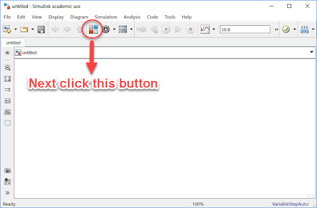
Once you click, a new window will pop up.

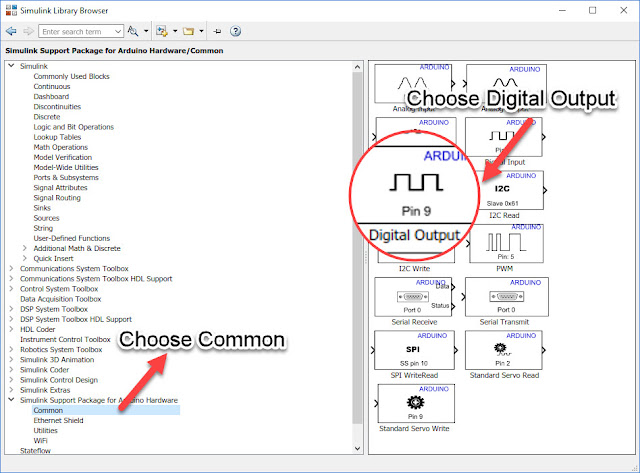
Next click "Simulink Support Package For Arduino Hardware".

Once you click this this, it will expand and dispalys another 4 more option.
Choose common and next choose the digital output.
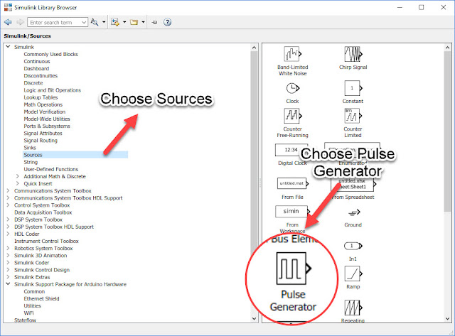
Now we have the Arduino digital output block. Next, we need to provide a pulse to it. In order to do this, we can use one of the blocks under the Simulink option, which is the Sources. Click sources and choose Pulse Generator.
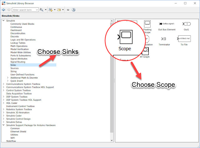
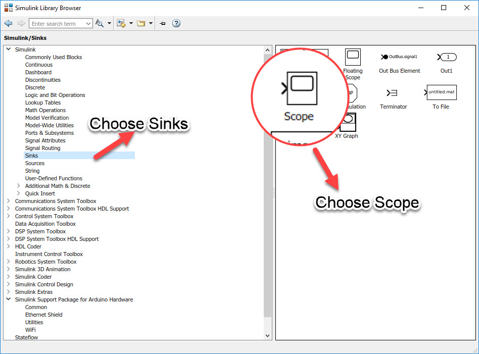
Once we have this, we need to measure the output from the pulse generator. To achieve this we can use the Sinks and choose Scope.
Once we have all of them in place, we can start to connect them.

The first step is to set up the pulse generator and measure its output with the scope.

The set up of the pulse generator is as shown in the image above. Next is to connect to the scope and check the output.
From the video, it shows the waveform which is created through the pulse generator. Here is the snapshot of the image. In the snapshot, it can be seen that the pulse is being generated every one second.

Once this done, the next step is to connect the pulse generator to the Arduino.

Once we connect the pulse generator to the Arduino, the Arduino pin need to be configured as well. We can use any pin which we desire but in this example, we choose Pin 13. The reason for Pin 13 is because it is connected to the internal LED. To achieve this we can simply double on the Arduino and change it.
Next step is to configure the hardware.

The Host Board Connection com port number depends on the individual PC. In my case, the com port number is 12.
The final step is to click the Deploy To Hardware Button.
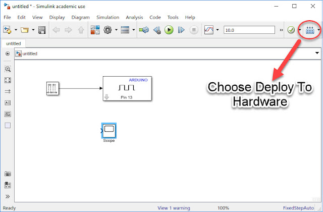
Once this button is clicked, it will compile and execute on the target board.
That's all for now, in our next tutorial we shall try to do some small projects using the Simulink.

The installation process is straightforward. Once you have installed it, the next step is to open the Simulink. The Simulink comes together with the Matlab as a package. But before that, we must install the Simulink arduino package. This can be downloaded from the Add-Ons.
In the Add-Ons window, type Arduino and wait for the search to complete. Once it is done, go to the left panel and look for the "Using Simulink" and choose the Simulink Fundamentals. The window will refresh and next choose the first option. Once it is installed open the Simulink.

Then click the choose the "Blank Model". And it will bring you to a new window.
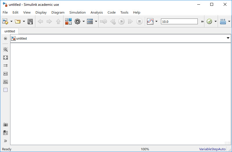
In this window choose the Library browser, which I have highlighted in below figure.

Once you click, a new window will pop up.

Next click "Simulink Support Package For Arduino Hardware".
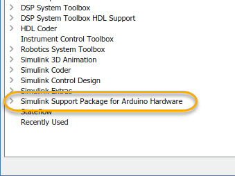
Once you click this this, it will expand and dispalys another 4 more option.
Choose common and next choose the digital output.

Now we have the Arduino digital output block. Next, we need to provide a pulse to it. In order to do this, we can use one of the blocks under the Simulink option, which is the Sources. Click sources and choose Pulse Generator.

Once we have this, we need to measure the output from the pulse generator. To achieve this we can use the Sinks and choose Scope.
Once we have all of them in place, we can start to connect them.
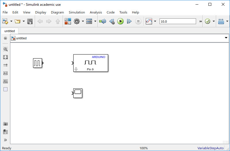
The first step is to set up the pulse generator and measure its output with the scope.
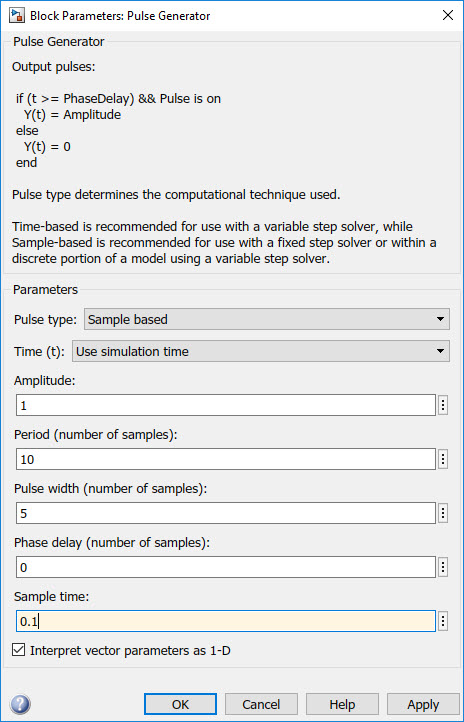
The set up of the pulse generator is as shown in the image above. Next is to connect to the scope and check the output.
From the video, it shows the waveform which is created through the pulse generator. Here is the snapshot of the image. In the snapshot, it can be seen that the pulse is being generated every one second.

Once this done, the next step is to connect the pulse generator to the Arduino.
Once we connect the pulse generator to the Arduino, the Arduino pin need to be configured as well. We can use any pin which we desire but in this example, we choose Pin 13. The reason for Pin 13 is because it is connected to the internal LED. To achieve this we can simply double on the Arduino and change it.
Next step is to configure the hardware.
The Host Board Connection com port number depends on the individual PC. In my case, the com port number is 12.
The final step is to click the Deploy To Hardware Button.
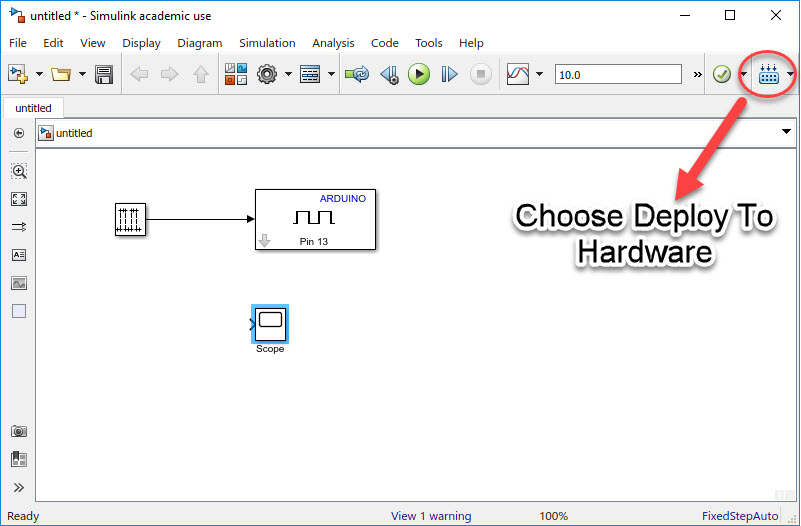
Once this button is clicked, it will compile and execute on the target board.
That's all for now, in our next tutorial we shall try to do some small projects using the Simulink.
Top Comments