


This is the second part of R2 User Guide.
Programming
1) Placing the target microcontroller
- Make sure the power switch of R2 is off, set the voltage selection jumper to the voltage you want and put your microcontroller in its socket at the right position as shown below.
* Place only 1 microcontroller at a time and the power switch should always be off when placing or removing microcontrollers.

- Please be noticed that the pin number 1 starts from the bottom left corner where the power switch is.
- Turn the switch on the R2 and check the heartbeat(Green) LED. Push the reset button of your Arduino if doesn’t heartbeat.
2) Burn Bootloader / Set Fuses
- Before loading your program, you need to configure your microcontroller by setting fuses and burning bootloader. It should only be done once for each microcontroller if you don’t need to change the configuration.
- Select your target microcontroller from the list under Tools > Board: of the Arduino IDE and set the option values such as Chip, Clock, B.O.D. Level and etc.
- If you are using SpenceKonde’s ATTinyCore as the Boards Manager to program ATtiny series, you can choose not to load bootloader. The board name with “Optiboot” loads the bootloader after setting fuses. All MCUdude’s Boards Managers but MicroCore normally load bootloader by default.

* The main function of the bootloader is making the microcontroller programmable via serial (TTL Level) interface. I normally choose not to load bootloader and save the memory.
* R2 doesn’t support external clock for ATtiny series while it supports all internal clocks and 16MHz external clock for ATmega series. Selecting unsupported clock may brick your microcontroller.
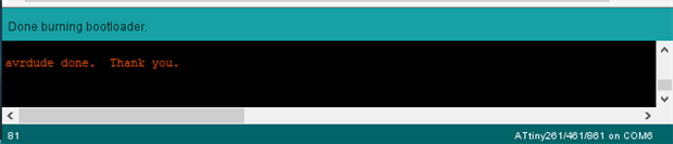
- Run Tools > Burn Bootloader to set fuses and load bootloader.
3) Uploading Sketch
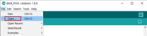
- Open(or write) a sketch. You can browse and open an existing sketch from File > Open.
* If you don’t press shift key down when you click on Upload button, you will sometimes get errors especially when you program ATmega series.
* Bootloader will be overwritten by your sketch if you upload a sketch via Arduino as ISP. You should use USB to Serial/TTL converter or other similar tools to upload sketch if you don’t want to get the bootloader overwritten. That’s why many people are using Arduino with no microcontroller to program theirs after burning bootloader.
- You will see “Compiling sketch”, “Uploading” and then “Done uploading” if nothing goes wrong.

- Your sketch will automatically be executed if it is uploaded properly.
4) Test(Optional)
- There is a built-in Test(Blue) LED on R2 and you can use it to see if your microcontroller is damaged, bricked or with error, especially after setting fuses.
* You shouldn’t do this test if you’ve already uploaded your sketch successfully otherwise you will have to upload it again as it is overwritten by the sketch for the test.
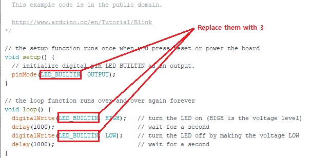
- Open Blink sketch under File > Examples > 01.Basics > Blink.

- Look for find all 3 ‘LED_BUILTIN’s from the source code and replace them with ‘3’ and upload the modified sketch to the target device. You can just use the attached ‘Blink_PIN3.ino’ sketch file instead of modifying the sketch by yourself as well.
- Your microcontroller is healthy and its clock frequency is correctly fused in most cases if the Test LED blinks in correct interval – ON for a second and OFF for another second.
Done! Have fun with your microcontrollers!!
Please see my other postings for more information.
ATmega/ATtiny Microcontroller Programming Shield for Arduino As ISP R1
ATmega/ATtiny Microcontroller Programming Shield for Arduino As ISP R2 - #1
ATmega/ATtiny Microcontroller Programming Shield for Arduino As ISP R2 - #2
ATmega/ATtiny Microcontroller Programming Shield for Arduino As ISP R2 - #3
ATmega/ATtiny Microcontroller Programming Shield for Arduino As ISP R2 - #5
FYI, this is not the last posting about R2.