


This will be the last posting about R2.
1. Limitations of R2 and the ideas for the enhancement.
a. R2 doesn’t support ATtiny with external clock.
I decided not to make R2 support ATtiny with external clock because I don’t use this combination. I normally use ATtiny when I need to make something tiny or simple and I don’t want to add any component not necessary.
Anyway, you may slightly modify the schematic to make the external clock supported. Please find ORANGE part of the schematic at the bottom of this posting. You may also notice that TEST LED may not work for DIP8(N) ATtiny25/45/85 and DIP10(N) ATtiny2323/4313 if they are set to use external clock.
b. Only 16MHz external clock is supported.
This can be resolved by making the crystal replaceable using a socket. I normally use a 3pin SIP Socket (2.54mm, through hole) even if it doesn’t look nice.
As R2 is just a tool to program microcontroller but the final product to be delivered to customers, the oscillation frequency doesn’t have to be very accurate. You may use any crystal with its CL around 15pF~20pF.
c. TEST LED doesn’t work with alternative pinouts.
MCUdude’s MightyCore boards manager and SpenceKonde’s ATTinyCore boards manager support alternative pinouts for ATtiny24/44/84 and ATmega8535/16/32/164/324/644/1284. TEST LED is connected to the pin where D03(Arduino Digital IO Pin #3) should be mapped to. If you burn bootloader - I actually
mean “set fuses” - with any of those alternative pinouts or your custom pinout, the pin connected to the LED is not D03 anymore!
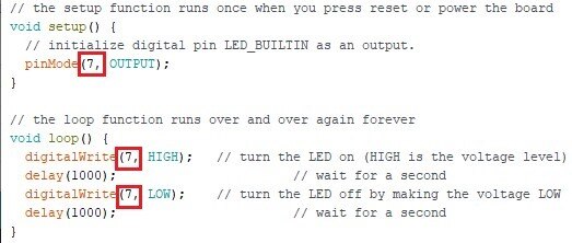
You may just modify the source code of Blink sketch to test the alternative pinouts as shown below.
- ATtiny24/44/84
This microcontroller’s default pinout is Clockwise but you may also choose Counterclockwise when you burn bootloader.

In this case, you should change the pin numbers in the sketch from 3 to 7.
- ATmega8535/16/32/164/324/644/1284
You can choose other pinouts than Standard pinout for this microcontroller. Standard pinout’s and Sanguino pinout’s D03 are mapped to the same physical pin #4 of the microcontroller but Bobuino pinout’s D03 is mapped to pin #17 where D11 of other pinouts are mapped to.

You should change the pin numbers in the sketch to 11 In this case.

You can also make change to the circuit if you need to use alternative pinouts often and too lazy to modify sketch. Please find PURPLE part of the schematic at the bottom of this posting.
2. Other topics
a. Protecting ArduinoISP sketch loaded to my Arduino.
I sometimes overwrite ArduinoISP sketch loaded to my Arduino with another sketch by mistake. I have an Arduino dedicated to programming with Arduino As ISP + R2. I sometimes forget to set Programmer to Arduino as ISP and forget to press SHIFT key down when I try to upload a sketch using Arduino IDE.
It turns my Arduino As ISP back to a normal Arduino. This is quite frustrating especially when it happens a couple of times or more even if it is not a big deal as I can fix this by reloading ArduinoISP sketch.
Is there a way to prevent it from happening? YES!!!
There is a built-in USB to Serial(TTL) converter on Arduino board. The microcontroller (ATmega328P) has its bootloader loaded and the bootloader loads program coming through the serial channel on top of the bootloader itself without getting overwritten.
It means the sketch won’t be loaded in this way if there is no bootloader.
Do you remember that loading a sketch with Arduino As ISP + R2 overwrites bootloader? Please see ATmega/ATtiny Microcontroller Programming Shield for Arduino As ISP R2 - #4 for detail.
That’s right. You can load ArduinoISP sketch to an ATmega328P microcontroller using Arduino As ISP + R2 to get rid of the bootloader and replace the microcontroller on your Arduino with it.
Done!!
b. Programming microcontrollers without getting bootloader overwritten.
There is no such way as long as you are using Arduino As ISP. Use a USB to Serial converter or other serial programmers in
the market. You can also use the built-in USB to Serial converter of your Arduino but you need to remove the microcontroller from your Arduino to do it.
3. ATmega/ATtiny Microcontroller Programming Shield for Arduino As ISP R2.1
Please find the modified schematic.

Please see my other postings for more information.
ATmega/ATtiny Microcontroller Programming Shield for Arduino As ISP R1
ATmega/ATtiny Microcontroller Programming Shield for Arduino As ISP R2 - #1
ATmega/ATtiny Microcontroller Programming Shield for Arduino As ISP R2 - #2
ATmega/ATtiny Microcontroller Programming Shield for Arduino As ISP R2 - #3
ATmega/ATtiny Microcontroller Programming Shield for Arduino As ISP R2 - #4