This article is meant to explain the architecture of the ATmega328P from Atmel for further projects on AVR Assembly programming
The overview:
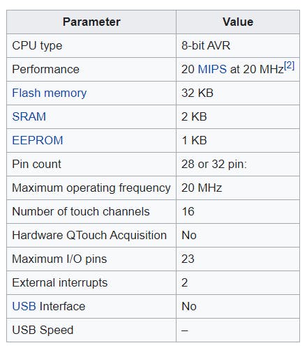
The high-performance Microchip picoPower 8-bit AVR RISC-based microcontroller combines 32KB ISP flash memory with read-while-write capabilities, 1024B EEPROM, 2KB SRAM, 23 general-purpose I/O lines, 32 general purpose working registers, three flexible timer/counters with compare modes, internal and external interrupts, serial programmable USART, a byte-oriented 2-wire serial interface, SPI serial port, a 6-channel 10-bit A/D converter (8-channels in TQFP and QFN/MLF packages), programmable watchdog timer with internal oscillator, and five software selectable power saving modes. The device operates between 1.8-5.5 volts.
By executing powerful instructions in a single clock cycle, the device achieves throughputs approaching 1 MIPS per MHz, balancing power consumption and processing speed.
Source: microchip.com
Features:
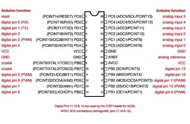
The Pinout:
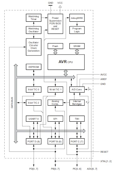
The code that we write in any language will be compiled into a binary file and will be stored in the available flash memory (non-volatile), thus retaining the code even if we disconnect the power supply from the MCU.
The AVR CPU executes the instruction from the flash memory one-by-one. The temporary variables that require memory will use the available memory in SRAM.
The MCU has various modules such as Timer/Counter, ADC (Analog-to-Digital Converter), DAC (Digital-to-Analog Converter), USART (Universal Synchronous Asynchronous Receiver Transmitter), SPI (Serial Peripheral Interface), Analog comparator, etc.
The Arduino can be programmed using the Arduino IDE. Either C or Assembly language can be used, but the upcoming projects mainly focus on Assembly programming and how the different modules present in the Atmega328P can be interfaced with.
The AVR Architecture:
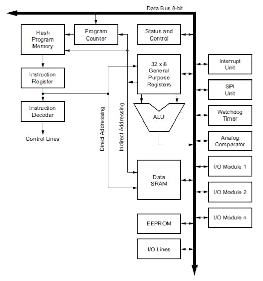
To maximize performance and parallelism, the AVR uses a Harvard architecture – with separate memories and buses for program and data. Instructions in the program memory are executed with a single level pipelining. While one instruction is being executed, the next instruction is pre-fetched from the program memory. This concept enables instructions to be executed in every clock cycle. The program memory is in-system reprogrammable flash memory.
-Datasheet
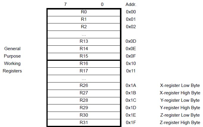
Registers and Pointers:
The C programming in Arduino IDE is very easy, and one can just declare variables and initialize them such as
int a=2;But in assembly programming it's different. You need to go deep into the hardware and write the code based on the availability of resources.
For storing such variables, ATmega328P makes use of the registers.
A register is nothing but a flip-flop (Memory storage element)
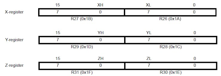
Then there are pointers to store the addresses of the memory locations, peripherals etc. Basically, the last 6 registers are used as pointers.
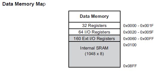
The Data memory map:
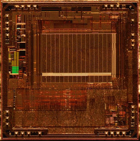
Die shot of ATmega328P:
There are other modules and registers which will be discussed as we learn various modules available.
Stay tuned!


Top Comments