

How to make your own self driving BeagleBot
So after my last post about how to make a WiFi Remote Controlled BeagleBot I have been working on a self controlled version.
So using an analogue IR sensor and an extra servo, you can now improve your BeagleBot so it can control itself and turn it into a sumo bot.
To start with here's a short video of my bot during one of its first tests just to show you all what we're aiming for....
The algorithm is fairly simple and basic, the bot just finds the centre of any object closer than about one metre and goes for the centre of it.
For the instructions for this project I am using nano, as it easier for everyone to use, but use whatever editor you want.
What we need?
| Product | Quantity | Order Code |
|---|---|---|
| Servo | 2 | 20753662075366 |
| BeagleBone Black | 1 | 24222282422228 |
| Battery Holders | 2 | 16506851650685 |
| DC Jack | 1 | 15683971568397 |
| Voltage Regulator | 1 | 14690421469042 |
| Micro Servo | 1 | 20753652075365 |
| Protoboard | 1 | 24746752474675 |
| LEDs | 2 | 24313932431393 |
| SD Card | 1 | 22902442290244 |
| AA Batteries | 1 | 22933442293344 |
| Sensor | 1 | 12438691243869 |
| Header | 2 | 34183883418388 |
| Sensor Contact Housing | 1 | 36161983616198 |
| Sensor Contacts | 3 | 36172103617210 |
| Materials to build the chassis | ||
Wire to take up to 3A | 30cm | |
Wire to take 500mA Or ribbon cable | 1-1.5m | |
| Wheels | ||
| TOOLS | ||
Soldering Iron | ||
| Solder | ||
| Hacksaw/Knife to cut the protoboard | ||
| Tools to cut and shape the chassis | ||
Glue | ||
| Wire Cutters & Strippers | ||
| Double Sided Sticky Tape |
Building the Chassis
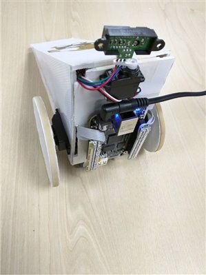
The chassis design is, of course, completely up to you, and what I have posted below is just a suggestion as to what you could do. My design was basically a wedge shape with the LEDs on the inside to light it up. finished it looks a bit like this......
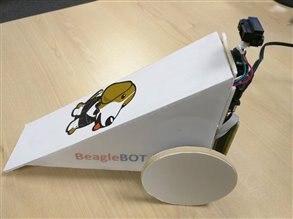
I made it with 3mm thick foam board, a craft knife, and some glue. The sides were just frames with paper and some translucent plastic on top to diffuse the LED light.
Simple, but I think it looks pretty good. See the video at the top for the LEDs in action.
Building it is both very simple and very fiddly.
Firstly cut and shape all of the sections you will need.
Make sure they all fit together properly and you know which bit goes where before even opening any glue!
Now glue them all together to form your basic shape then add any extras/graphics you want to add
Try not get any glue on the outside else you will see it even after it has dried.
The sides of my bot are made from those translucent folders you can get from stationers with the graphics printed out on a piece of A4 paper and stuck on top. Pretty simple and cheap but I think the effect works fairly well thanks to high brightness LEDs. I also cut out a frame for the sides just to give it some structure.
Building the Electronics
This is the most fiddly I thought as I had to do it all on protoboard, which I don't have a lot of experience with, but it's easy enough if you don't try cram it all into one corner (like I tried to do), because then I spent a few hours problem finding.
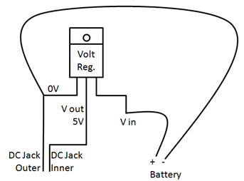
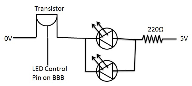
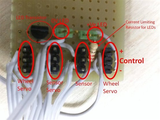
Anyway, Here is the circuit diagram for the power circuit and the LEDs. The other connections are for the connector I made. The connector is just two strips of protoboard with headers that clip into the BBB then bring the connections I need onto the protoboard inside where there are headers for the servos, sensor, etc. This is to keep the outside as neat as possible, but it works just as well if you use jumper cables to connect directly to the BBB. Also remember that batteries are connected in parallel to get max capacity so they last longer. You can add more than two battery packs if you want in order to make the bot go for longer, but it takes a lot of room and weight.
If you think something is missing then, as always, please shout up.
Voltage Regulator Pinout
LED circuit
Pin Mapping
| Connection | BBB Pin |
|---|---|
| Servo 1 V+ | 5V+ any |
| Servo 1 control | Pin9_13 |
| Servo 1 grnd | 0V any |
| Servo 2 V+ | 5V+ any |
| Servo 2 control | Pin8_14 |
| Servo 2 grnd | 0V any |
| sensor servo V+ | 5V+ any |
| Sensor servo control | Pin9_22 |
| Sensor servo grnd | 0V any |
| Sensor V+ | 5V+ any |
| Sensor Vout | Pin9_40 |
| Sensor grnd | 0V any |
| LEDs V+ | 5V any |
| LEDs transistor gate | Pin8_10 |
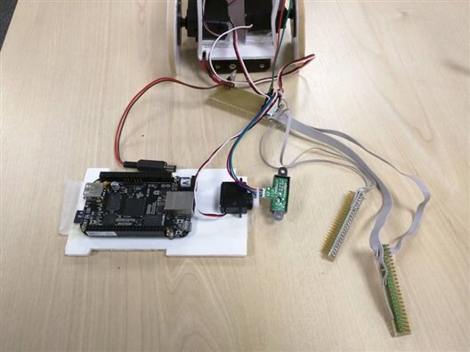
My Connector board - takes the wires from my BBB connectors and routes them to the headers for the servos and sensor and LEDs
Assembly
Finally we are ready to assemble the bot. For this you will need pretty much everything.....
| Assembled Chassis |
Soldered Electronics Protoboard + connector + Battery holders |
| 2x Wheel servos |
| 1x 180° servo |
IR Sensor |
| Beagle Bone |
| LED board |
| PCB mounters |
| Wheels |
| Ball Bearing caster |
So to start I glued and stuck the wheel servos to the chassis. The plastic of the servo casing didn't stick very well using glue so I used double sided sticky tape for that.
Next I stuck the battery casings to the base of the chassis using double sided tape (again the glue didn't stick the plastic very well).
Then I fixed the beagle bone by making four holes in the back of the chassis to line up with the mounting holes of the BBB, Then I screwed the beagle bone on using the PCB mounting bolts and some washers to prevent the bolts from ripping the back plate too much.
Next I stuck the Sensor Servo to the top of the back panel and put the sensor on top.
Then I screwed the servo horn for the wheels onto the servo shaft, then glued the wheels I have made onto the horn, and stuck the ball bearing caster to the front underside.
Now I glued the LED board onto the inside of the chassis.
Finally I plugged all of the connectors onto the Protoboard, and carefully and neatly stashed all of the wires and everything inside the case and closed the back panel to keep everything in.
Installing Dependencies
So first we have to install Debian. I prefer to work on an SD card so I can easily backup at regular intervals in case something goes wrong. I installed THIS image onto the card. Just flash it onto an SD card and you're good to go.
Once booted we need to install the one library we need for the GPIOs.
Into the console type....
apt-get install adafruit_GPIO
Once installed we can get started on everything else.
Python Scripts
So for this, I have a few scripts.
One is running the algorithm and controlling orchestrating everything. Another script is a library I have written to control the wheel servos properly, and the other script is to control the LEDs through a normal GPIO. A bit complex and round about but it works well. If you find a better way to do it then please share below.
Controlling the LEDs
So as the BBB only has three PWM chips controlling six outputs, we have a bit of a problem. Each PWM chip can only control two outputs if it is set to its default frequency else it is limited to one output only. So the situation is this. We have three servos running on three PWM pins. We have to change the frequency from the default because the servos do not work well on that frequency. This means each chip can only control one pin, Therefore we only have three PWM pins to play with, so the servos take those, which means we have to use a GPIO to control the LEDs.
I can't think of a better way to do this, but perhaps you guys can.
So, this LED program will need to know a frequency and a duty cycle. I pass the frequency as wavelength, the time for one on&off pulse, as this is what I have used in the program.
Into the terminal type the line below to open a new file for editing
nano ~/led.py
The script is as follows, I have tried to comment it comprehensively and concisely but shout up if you spot an error or think anything should be explained better.
# Works by reading files roughly similar to the system PWM files and manually creating the GPIO pulses to drive the LEDs
import Adafruit_BBIO.GPIO as GPIO    # Import the library we need to control the GPIO that the LEDs are attached to.
import time                          # We are using the time library to time the pulses, obviously
GPIO.setup("P8_10",GPIO.OUT)          # Sets the LEDs pin as an output pin
GPIO.output("P8_10",GPIO.LOW)        # Sets the LEDs pin LOW, turning them off
while True:                          # This is the main loop
  file=open("LED_DUTY","r")          # Opens the file that controls the duty cycle for the led
  duty=float(file.read())            # Grabs the duty cycle from the file
  file.close()                        # Close the duty cycle file
  file=open("LED_PERIOD","r")        # Opens the file that controls the Period for the LED
  period=float(file.read())          # Grabs the period from the file
  file.close()                        # Closes the Period file
  on=period*duty                      # Calculates the time the LEDs need to be on for each pulse
  off=period-on                      # Calculates the time the LEDs need to be off for each pulse
  #print (on,off)                    # Used for debugging to show on/off times of the pulse
  if duty!=0: GPIO.output("P8_10",GPIO.HIGH) # Checks if the duty is not 0 (short cut for permanent off), turns LED on.
  time.sleep(on)                      # Pause for the on time of the pulse
  GPIO.output("P8_10",GPIO.LOW)      # Turn the LEDs off
  time.sleep(off)                    # Pause for the off time of the pulse
  # Loop back to the main loop to repeat
We also need to create the files for the led.py script to read.
Into the terminal type
echo 1 > ~/LED_PERIOD
echo 0.5 > ~/LED_DUTY
this will create the two new files that we need for the LED.py scripts
Controlling the servos
After getting the sensor data we need to control the servos. I have done this using a python module of its own just to make things simple though you could put all this into the main script as functions of their own if you'd like.
To make this module type this into the console terminal
nano ~/move.py
Then type this into the file
#P8_13 Servo 1
#P9_14 Servo 2
debug=False    # Change to True if debug messages are needed


def duty(percent):      #when called, this function converts percentage of power (0=full reverse, 50=stop, 100=full forward) to the actual duty cycle
  return(100 - ((float(percent) / 100) * duty_span + duty_min))    #Returns the duty cycle when the speed is passed as a percentage


# Functions for moving
#  when called they correct the servo duty cycle
#  the duty function is called so we can use % instead of actual duty cycle values to make it easier to interpret the speed of the servos from the code
def forward():    #Makes the bot go straight ahead
    PWM.start("P8_13", 95.0, 60)  # initiates the servos
    PWM.start("P9_14", 95.0, 60)
    PWM.set_duty_cycle("P9_14", duty(65)) # Sets servo 1 to go forward
    PWM.set_duty_cycle("P8_13", duty(35)) # Sets servo 2 to go forward
    if debug==True:return("Forward")      # returns "forward" if debug messages are turned on
    else:return()                        # returns nothing if debug messages are turned off


def left():    # Turns the bot on the spot anti-clockwise
    PWM.start("P8_13", 95.0, 60)  # initiates the servos
    PWM.start("P9_14", 95.0, 60)
    PWM.set_duty_cycle("P8_13", duty(47)) # Sets servo 1 to go backwards
    PWM.set_duty_cycle("P9_14", duty(47)) # Sets servo 2 to go forwards
    if debug==True:return("Left")        # returns "left" if debug messages are turned on
    else:return()                        # returns nothing if debug messages are turned off


def right():    # Turns the bot on the spot clockwise
    PWM.start("P8_13", 95.0, 60)  # initiates the servos
    PWM.start("P9_14", 95.0, 60)
    PWM.set_duty_cycle("P9_14", duty(53)) # Sets servo 1 to go forwards
    PWM.set_duty_cycle("P8_13", duty(53)) # Sets servo 2 to go backwards
    if debug==True:return("Right")        # returns "right" if debug messages are turned on
    else:return()                        # returns nothing if debug messages are turned off


def backward():    # Reverses the bot
    PWM.start("P8_13", 95.0, 60)  # initiates the servos
    PWM.start("P9_14", 95.0, 60)
    PWM.set_duty_cycle("P9_14", duty(35))    # Sets servo 1 to reverse
    PWM.set_duty_cycle("P8_13", duty(65))    # Sets servo 2 to reverse
    if debug==True:return("Backward")        # Returns "backwards" of  debug messages are turned on
    else:return()                            # Returns nothing if debug messages are turned off


def stop():    # Stops the bot
    PWM.start("P8_13", 95.0, 60)  # initiates the servos
    PWM.start("P9_14", 95.0, 60)
    PWM.set_duty_cycle("P8_13", duty(50))    # Sets servo 1 to stop
    PWM.set_duty_cycle("P9_14", duty(50))    # Sets servo 2 to stop
    if debug==True:return("Stop")            # Returns "stop" if debug messages are turned on
    else:return()                            # Returns nothing if debug messages are turned off


def servo(angle):    # This function Controls the servos when passed the angle that the sensor detects the object at
  if debug==True:print(angle)    # If debug messages are on then print the angle passed
  if angle==-2:    # If angle is -2 (object too close), then reverse
      print(backward())    # Reverse the bot and print any returned value.
  elif angle == -1:    # If angle is -1 (no object found in this 180° view) then turn around
      if debug==True:print("Turn Around")    # if debug messages are turned on then print "turn around"
      print(right())    # Turn the bot clockwise and print any returned values
      time.sleep(1)    # wait for 1 second whilst bot is turning
      print(stop())    # Stop the bot from turning and print any returned values
  elif angle > 3806000:    # If angle is to the left of (centre+error margin)
      print(left())    # Turn left and print any returned values
  elif angle < 3694000:    # If angle is to the right of (centre+error margin)
      print(right())    # Turn right and print any returned values
  elif 3806000 >= angle >= 3694000:    # If object is in front of bot within error margin
      print(forward())    # Go forwards towards object and print any returned values


# This Section is run on import
import Adafruit_BBIO.PWM as PWM    #imports the required python libraries, including the PWM libraries to control the servos
import time
duty_min = 92.4    #sets the min and max duty cycle for the servos
duty_max = 99.9
duty_span = duty_max - duty_min    #calculates the range between the min and max duty cycles
stop()                              # Stops the servos to stop the bot just in case the servos are currently moving.
Okay, so now we have a module that we can pass an angle to and it will control all the servos for us.
The angle we pass is actually the period of the micro servo the sensor is attached to, that is why it is such a weird number.
Controlling the Sensor Servo
After having a lot of problems with the Adafruit PWM library and the sensor servo, I decided to write my own library that changed the PWM system files directly. After a bit of research I realised that it was actually very simple with BBB.
Open a new file using this command in the terminal
nano ~/PWM.py
In this file type....
import glob          # Glob is needed to get the path to the system files


def init():          # Initiates the BBB GPIO slots
  file=open("/sys/devices/bone_capemgr.9/slots","w")    # opens the GPIO slot control file for editing
  file.write("am33xx_pwm")          # Enable the PWM pins
  file.close()          # Close the GPIO control file


def start(pin):    # starts the PWM pin if not already started, must be done before that pin can be controlled
  try:    # will return error if pin has already been started, try except handles this error
      file=open("/sys/devices/bone_capemgr.9/slots","w")    # opens the file that controls the GPIOs
      file.write("bone_pwm_"+pin)    # initiate the PWM pin required
      file.close()    # close the GPIO control file
  except IOError:    # If the pin has already been started, then it will return error, this handles that error
      print("file exists, pins already started")    # tell user pin is already started
  run(pin,"1")    # starts the PWM on the new pin


def period(pin,period):    # sets the period for the PWM pin passed
  path=str("/sys/devices/ocp.*/pwm_test_"+pin+".*/period")    # sets the path to the pins period file, needs to use wildcards as path is different each boot
  path=str(glob.glob(path)[0])          # because the ocp.* value changes every boot we need to use glob.glob to evaluate the correct path
  file=open(path,"w")          # opens the pins period file for writing
  file.write(str(period))    # Writes the period into the period file
  file.close()    # Close the period file
  file=open(path,"r")    # open the period file for reading
  print(file.readlines())    # prints the period in the period file - used during debug but kept as is fairly useful just to know it has changed properly
  file.close()    # close period file


def duty(pin,duty):    # sets the duty for the PWM pin passed
  path=str("/sys/devices/ocp.*/pwm_test_"+pin+".*/duty") # sets the path to the pins duty file, needs to use wildcards as the path is different each boot
  path=str(glob.glob(path)[0])    # because the ocp.* value changes each boot we need to use glob.glob to evaluate the correct path
  file=open(path,"w")    # opens the pins duty file for writing
  file.write(str(duty))    # writes the duty into the duty file
  file.close()    # closes the duty file
  file=open(path,"r")    #opens the duty file for reading
  print(file.readlines())    # prints the duty in the file - used during debugging but kept as is fairly useful just to know it has changed correctly
  file.close()    # closes the duty file


def run(pin,val):          # sets whether the PWM pin is enabled or not
  if str(val)!= "1" and str(val) != "0":    # The only valid values are 1 and 0, checks if the value passed is valid or not.
    print("Error: run must be 1 or 0")    # if the value is not valid tell user
    return(-1)    # return error code, invalid value for run
  path=str("/sys/devices/ocp.*/pwm_test_"+pin+".*/run")    # sets the path to the pins duty file, needs to use wildcards as the path is different each boot
  path=str(glob.glob(path)[0])    # because the ocp.* value changes each boot we need to use glob.glob to evaluate the correct path
  file=open(path,"w")    # opens the pins run file for writing
  file.write(str(val))    # writes the run value into the duty file
  file.close()    # closes the pins run file
  file=open(path,"r")    # opens the pins run file for reading
  print(file.readlines())    # reads and prints the run value, useful as it checks if the run status was updated correctly
  file.close()    # closes the pins run file


def stop(pin):    # shortcut command to stop pin
  run(pin,"0")    # stops the pin but setting run to 0
We can now import this module and use it to control the servo that has the sensor on it.
The Main Script
This is the script that coordinates and controls everything. It also has the algorithm that controls the sensor and servo. So here goes, I've tried to comment it completely but shout up if you find an error, or don't understand anything.
Into the linux terminal type
nano MicroServo.py
Into this file type
#!/usr/bin/python

import time    # Imports the needed modules
import PWM      # Imports our own PWM  module
import Adafruit_BBIO.ADC as ADC    # Imports Adafruit's ADC library for reading the sensor
import move, os    # Imports more needed libraries
os.system("python /home/debian/led.py &")    # Starts the LED controlling script in the background
if os.path.isdir("/sys/class/pwm/pwm2"):    # if the PWM pins are already started
  print "pwm enabled"                          # tell user that the PWM pins are already started
else:    # If the PWM pins are not yet enabled
  file=open("/sys/class/pwm/export","w")    # Open the file that controls the PWM pins
  file.write("2")    # Enable the PWM pin we are going to use
  file.close()    # Close the file


servo_pin = "P9_22"    # Sets the servo pin
adc_pin = "P9_40"    # Sets the ADC/sensor pin
value_real= 0.0    # The value of the sensor 0-1.8V
mid_angle=-1    # Defines variable for storing the central angle of the object detected
PWM.init()    # runs init function
PWM.start(servo_pin)    # Initiates the Servo Pin
PWM.period(servo_pin,"5000000")    #  sets the sensor servo period to 5ms


def microserv(duty):    # Function to set the duty for the servo
  #print (servo_pin)
  PWM.duty(servo_pin,duty)    # Sets the servo duty

def LED(duty,period=1):    # Allows the setting of the LEDs duty cycle and period
  f_duty=open("LED_DUTY","w")    # Opens the LEDs duty cycle file for editing
  f_duty.write(str(duty))    # write the new duty_cycle to the LED duty_cycle file
  f_duty.close()    # close the duty cycle file
  f_period=open("LED_PERIOD","w")    # open the period file for editing
  f_period.write(str(period))    # Write the new period to the period file
  f_period.close()    # close the period file


def read_ADC():    #ADC read function definition
  value = ADC.read(adc_pin)    # Reads the ADC Value
  value = ADC.read(adc_pin      #bug in ADC driver, needs to read twice to get current value
                                # The first read updates the file, the second read gets the new value
  print value
  return value    # returns the ADC value


LED(0.5,1)    # sets the Initial LED period and duty cycle
while True:    # Main run time loop
  angle = 2870000    # set the initial servo angle, Full right
  ADC.setup()    # start the ADC pin
  microserv(angle)    # set the servo to the initial angle
  time.sleep(0.4)    # time pause to allow servo to get to angle
  min_dist=0    # set minimum distance to 0 - used to tell if we have detected an object this run or not
  while angle < 4540000:    # sets servo to full right
    angle = angle + 56000;    # step servo one step left
    microserv(angle)    # send sensor servo to position set in angle var
    time.sleep(0.06)    #Delay to allow servo to reposition
    distance = read_ADC()    # Read the ADC value
    if distance>0.11:    # if an object is detected close enough for it to be a significant reading
      print "object detected"    # tell user object detected
      start_angle=angle    # take note of current angle
      while distance>0.11 and angle < 4540000:    # while object is detectable and servo is not already fully left
        angle = angle + 56000;    # set sensor servo 1 step left
        microserv(angle)    # reposition servo to set angle see ^
        time.sleep(0.06)    #  pause whilst servo moves
        distance=read_ADC()    # read sensor value
        if distance>min_dist: min_dist=distance    # if current distance is closer than the previous closest then update min_dist
      end_angle=angle    # once object is out of the significant range then set the end_angle of the object
      mid_angle=(end_angle+start_angle)/2    # find the mean average of the start and end angle in order to find the centre of the object
      move.servo(mid_angle)    # call the wheel servo control module and pass the angle of the object. this will reposition the bot to turn towards the object
      if mid_angle>3700000: angle=start_angle-280000    # if the mid angle is not fully right then set the sensor servo angle to the start angle and bit further to make sure we get the edge
      else: angle=start_angle    # set the sensor servo angle to the start angle and bit further to make sure we get the edge
      if angle<2870000: angle = 2870000    # if the angle is less than the minimum allowed by the servo then set it to the minimum, saves wrecking the servo.
      microserv(angle)    # send the servo to the angle set
      if 3638000<=angle<=3862000: LED(0.5,0.1)    # if the angle is dead ahead with a bit of margin, flash the LEDs fast and small duty cycle.
      else: LED(0.8,0.3)    # if the object is not straight ahead then set the LEDs to flash at a normal rate
      time.sleep(0.15)    # pause to allow the servo to reposition
    else: LED(0.5,1)    #if no object detected at all then flash slowly


    #If enemy straight ahead, stop scanning. Range can be tweaked
    while 3806000 >= mid_angle >= 3694000 and distance>0.35:    # if object was dead ahead then stop scanning left to right and just take range ahead until distance is too far
      move.servo(mid_angle)    # pass angle to abject to the wheel servo control module
      microserv(3750000)    # set sensor to look straight ahead
      distance = read_ADC()    # read the distance to the object

    #if too close, back up. Return -2, condition for reversing wheels.
    if(distance > 0.11):
      move.servo(-2)

  move.servo(-1)    # if scan got no hits then spin right around
  time.sleep(2)    # wait 2 seconds whilst bot spins
  move.stop()    # stop spinning then return to while true loop (line 47)
PWM.stop(servo_pin)    # if something goes wrong and while true fails then  stop servos to prevent run away bot.
Finishing off and running
So make sure everything is assembled properly.
Boot up your board, and login as root.
Use cd to navigate to where ever you wrote all the files
Use this command to start your script, then back off as either your bot goes round in circles, attacks phantom bots, or hopefully, works perfectly first time.
python MicroServo.py
when you have had enough of your bot running around, plug your uart cable back in and use ctrl+c to stop the python script. If the wheels keep going then either power off the board or type the following into the console
$ python

>>> import move
>>> move.stop()
Well I hope it all works for you. If not then please leave a constructive, helpful comment below and I'll see if I or someone else on the community can help.
Any Improvements or suggestions please also leave a comment below.
If you make this or something similar then please, please, please tell me how it went, and please leave a little pic/video/link in your comment.
