


Introduction:
One of the key feature of Maxim MAX-32650 micro-controller is 24-bit TFT LCD controller with color and monochrome display support. So in order to test the capabilities of this builtin 24-bit TFT controller, the best option is to run it at full color range. 24-bit high quality BMP images stored in an SD-card are used to conduct all the tests and to find the limitations.
Details:
LCD-TFT controller of MAX-32650 is capable of displaying 1/2/4/8/16 and 24 bit image data. In 1/2/4/8 bit mode it uses has up to 256 color palette RAM to simplify the image data manipulation. Whereas in 16 or 24bit raw data is required to display to image. At maxim color quality setting of 24-bit there are two options to fill up the 32bit wide display buffer i.e. lower 24bit contain color data and upper 8-bit are unused OR compact 24-bit mode in which it contains 1-1/3 pixel data.
In these tests display is used in both 24-bit compact and default mode. In compact 24-bit mode user can directly transfer the raw BMP/BIN image data into display buffer and also the buffer size will be 76800 byte smaller than default mode. In default mode user need to add 0xff after every three byte to skip the upper 8-bits of each 32-bit display buffer register.
Code:
All the code used to decode the BMP image file, placed in an SD-card, is based on Maxim MAXFAT and MAXSDHC libraries. I have received the REV.3 of MAX32650 EV-Kit which has the added functionality of enabling and disabling the SD-card power supply (P3_5) as well select able pull-up reference voltage (JP14). Due to modification in PCB layout of the SDK SDHC example doesn't work. In order to use the SDHC functionality with general SD-card before the initialization of SDHC module the JP14 should be at 3V3 position and set the P3_5 HIGH to enable the SD-card power supply. Add the code given below to enable the power supply of SD-card.
/* Setup SDHC power pin. */
gpio_sdhc_pwr.port = PORT_3;
gpio_sdhc_pwr.mask = PIN_5;
gpio_sdhc_pwr.pad = GPIO_PAD_NONE;
gpio_sdhc_pwr.func = GPIO_FUNC_OUT;
GPIO_Config(&gpio_sdhc_pwr);

/* Set the SDHC power pin high. */
GPIO_OutSet(&gpio_sdhc_pwr);
Basic function to decode the BMP image file then stored the RAW image data only in a buffer for further processing if required is given below. In this code it is assumed that the image file we are reading is of same size as our display and we have already created a buffer (with uint8_t* Address address) of required length. Another important thing is don't use the LCD display buffer for the image data after the initialization of LCD controller. If it is necessary to use that buffer to read the data then disable the display first then pass it to function given below otherwise it will result in a hard-fault.
FRESULT read_BMP(uint8_t *Address, const char* BmpName)
{
  uint32_t size = 0, i1 = 0;

    if(!mounted) {
        mount();
    }

    printf("Reading BMP file %s\n",BmpName);

    err = f_open(&file, (const TCHAR *)BmpName, FA_READ);
    err = f_read(&file, Address, 50, &bytes_read);

  /* Read bitmap size */
  size = *(uint16_t *) (Address + 34);
  size |= (*(uint16_t *) (Address + 36)) << 16;

  /* Get bitmap data address offset */
  index = *(uint16_t *) (Address + 10);
  index |= (*(uint16_t *) (Address + 12)) << 16;

    printf("BMP image data size: %d, data offset: %d\n\n", size, index);

    err = f_read(&file, Address, index-50, &bytes_read);
    uint32_t temp=0;
  do{
    if (size < 512){
      i1 = size;
    }
    else{
     i1 = 512;
    }
    size -= i1;

        err = f_read(&file, Address + temp, i1, &bytes_read);
        temp +=bytes_read;
  }
  while (size > 0);
    err = f_close(&file);
    printf("BMP file reading complete!\n");
  return err;
}
We can also use the simplified way the BMP image data read by generating the bin using online tool (HERE). And the code to read BMP image BIN data file is also provided below.

Figure-1: The online tool settings required to generate a image data C-array file to use with default 24-bit display setting
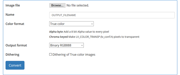
Figure-2: The online tool settings required to generate a image BIN file to use with default 24-bit display setting
FRESULT read_BIN(uint8_t *Address, const char* BinName)
{
  uint32_t size = 0, i1 = 0;

    if(!mounted) {
        mount();
    }

    printf("Reading BIN file %s\n",BinName);

    err = f_open(&file, (const TCHAR *)BinName, FA_READ);
    size = IRAM_BUFFER_SIZE;

    printf("BIN image data size: %d\n\n", size);
    err = f_read(&file, Address, 4, &bytes_read);

    uint32_t temp=0;
  do{
    if (size < 512){
      i1 = size;
    }
    else{
     i1 = 512;
    }
    size -= i1;

        err = f_read(&file, Address + temp, i1, &bytes_read);
        temp +=bytes_read;
  }
  while (size > 0);
    err = f_close(&file);
    printf("BMP file reading complete!\n");
  return err;
}
LCD display setting and function used to configure LCD controller in 24-bit color mode:
// CLCD
#define PANEL_WIDTH         320
#define PANEL_HEIGHT        240
#define IRAM_BUFFER_SIZE    (PANEL_WIDTH * PANEL_HEIGHT * 4)
#define LCD_BPP                            BPP24

uint8_t framebuffer_1[IRAM_BUFFER_SIZE + 31];    // LCD display buffer
uint8_t framebuffer_2[IRAM_BUFFER_SIZE + 31];    // BMP image data buffer required to read image data stored in sd-card

// color palette is required for proper functioning of SDK CLCD functions even in 16/24-bit mode
/** Color palette for the image. */
uint32_t palette[] =
{
   0xFFFFFF
};

volatile uint32_t    base_addr_1 = 0;     // 32-bit address of LCD-buffer
volatile uint32_t    base_addr_2 = 0;     // 32-bit address of BMP image data buffer "OPTIONAL"
clcd_cfg_t           panel; /**! Panel configuration structure */


void display_setup(void)
{
    panel.width       = PANEL_WIDTH;    /**! Set the size of the panel in pixels */
    panel.height      = PANEL_HEIGHT;   /**! Set the width of the panel in pixels */
    panel.frequency   = 6400000;        /**! minimum panel supported frequency */
    panel.vfrontporch = 2;              /**! the vertical front porch for the display */
    panel.vbackporch  = 2;              /**! the vertical back porch for the display */
    panel.vsyncwidth  = 10;
    panel.hfrontporch = 12;             /**! Set the horizontal front porch width */
    panel.hbackporch  = 2;              /**! Set the horizontal back porch width */
    panel.hsyncwidth  = 70;             /**! Set the horizontal sync width */
    panel.palette     = palette;
    panel.paletteSize = sizeof(palette)/sizeof(uint32_t); /** set the palette size in words */
        panel.bpp                 = LCD_BPP;

    /** Init and config CLCD */
    CLCD_Init(NULL, &panel);
/* Uncomment the line below to use 24-bit compact mode for detail visit page 259 of MAX-32650 user guide*/
//    MXC_CLCD->ctrl |= MXC_F_CLCD_CTRL_C24;    // enable 24bit compact setting

    /** Set CLCD frame base address */
    CLCD_SetFrameAddr((void*)base_addr_1);

    /** Enable the CLCD */
    CLCD_Enable();
}
Optional code:
Code to get all the important parameters of any BMP file stored in SD-card.
Function to read any file from SD-card (maxim of 512 bytes of data and obtained from SDK SDHC example):
FRESULT readFile(char* file_name, uint8_t* data, uint32_t length)
{
    if(!mounted) {
        mount();
    }
    printf("Reading file %s with length %d\n",file_name, length);

    if((err = f_open(&file, (const TCHAR *)file_name, FA_READ)) != FR_OK){
        printf("Error opening file: %s\n", FF_ERRORS[err]);
        f_mount(NULL, "", 0); return err;
    }
    printf("File opened!\n");

    if((err = f_read(&file, data, length, &bytes_read)) != FR_OK){
        printf("Error writing file: %s\n", FF_ERRORS[err]);
        f_mount(NULL, "", 0); return err;
    }
    printf("%d bytes read from file!\n", bytes_read);

    if((err = f_close(&file)) != FR_OK){
        printf("Error closing file: %s\n", FF_ERRORS[err]);
        f_mount(NULL, "", 0); return err;
    }
    printf("File Closed!\n");
    return err;
}
Code to read and print all the important parameters of any BMP image file:
uint32_t file_size=0, image_size=0, image_offset=0, image_width=0, image_height=0, image_bpp=0;
uint8_t image_data[50];
readFile("image.bmp", image_data, sizeof(image_data));
file_size = image_data[5]<<24 | image_data[4]<<16 | image_data[3]<<8 | image_data[2];
printf("0x%02x | 0x%02x | 0x%02x | 0x%02x | file size: %d\n", image_data[5], image_data[4], image_data[3], image_data[2], file_size);

image_offset = image_data[13]<<24 | image_data[12]<<16 | image_data[11]<<8 | image_data[10];
printf("0x%02x | 0x%02x | 0x%02x | 0x%02x | image data offset: %d\n", image_data[13], image_data[12], image_data[11], image_data[10], image_offset);

image_width = image_data[21]<<24 | image_data[20]<<16 | image_data[19]<<8 | image_data[18];
printf("0x%02x | 0x%02x | 0x%02x | 0x%02x | image width: %d\n", image_data[21], image_data[20], image_data[19], image_data[18], image_width);

image_height = image_data[25]<<24 | image_data[24]<<16 | image_data[23]<<8 | image_data[22];
printf("0x%02x | 0x%02x | 0x%02x | 0x%02x | image height: %d\n", image_data[25], image_data[24], image_data[23], image_data[22], image_height);

image_bpp = image_data[29]<<8 | image_data[28];
printf("0x%02x | 0x%02x | image bpp: %d\n", image_data[29], image_data[28], image_bpp);

image_size = image_data[37]<<24 | image_data[36]<<16 | image_data[35]<<8 | image_data[34];
printf("0x%02x | 0x%02x | 0x%02x | 0x%02x | image height: %d\n", image_data[37], image_data[36], image_data[35], image_data[34], image_size);
Demo:
/.
.
.
.
Conclusion:
Display work same as mentioned in the datasheet only if image is stored into display buffer before enabling the builtin controller of MAX-32650. User can only update the display buffer with flash stored image data buffer after the initialization of LCD controller. After the initialization of LCD controller the rest of the code execution especially working with other external devices (SD-CARD, HYPERBUS RAM, SRAM, FLASH etc) will cause random hard-fault after random intervals. So in other word if display is initialized then user need to take of few things before executing the rest of the code. Best way to access external devices while avoiding hardfault is, only use the images with the zero red color. Or else user can choose the workarounds mentioned in MAX-32650 errata sheet as shown below.

TFT LCD is using P2_14, P2_15 and P2_16 GPIO while onboard PMIC MAX77650 is connected at P2_7 and P2_8 in EV-Kit. And both of these workaround are also tested by removing the red component from display buffer data and executing the code from SRAM instead of flash but it doesn't solve the problem of hard-fault when several image are continuously read from SD-card and displayed on the TFT LCD. Also there is no details about the Hyperbus RAM data corruption when LCD controller is in initialized state and data is read from Hyperbus RAM (details HERE).
The only possible way of using TFT LCD while avoiding hard-fault is using maximum of 8-bit color setting, avoid updating the entire display area at once and communicate with external devices only when LCD is in disabled state.
Useful Links:
MAX-32650 user manual: https://pdfserv.maximintegrated.com/en/an/AN6766.pdf
Maxim MAX-32650 Errata sheet: https://datasheets.maximintegrated.com/en/errata/MAX32650-2_REVA1_(Rev_1).pdf
Online tool to convert picture into c-array/bin: https://littlevgl.com/image-to-c-array
BMP image file content information: https://en.wikipedia.org/wiki/BMP_file_format
MAX32650 EV-kit road test review: Maxim MAX32650-EVKIT - Review