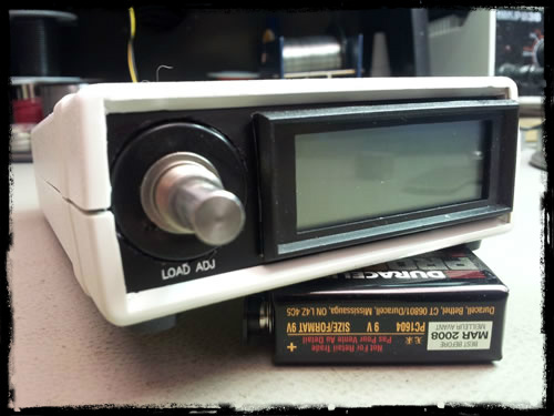
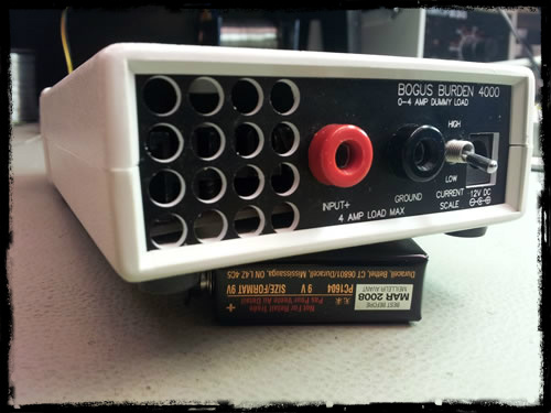
BogusBurden4000 – Finished Product
PROJECT BACKGROUND / ACKNOWLEDGMENTS:
A while back I had subscribed to a very interesting video blog called the EEVBLOG (Electronics Engineering Video Blog). The blog is created and is run by an interesting Australian fellow by the name of Dave Jones. In one of his blogs Dave discusses a little side project of his – a simple constant current electronic load. Such a device can come in very handy when testing batteries and power supply circuits–among other things. In episode #102 of EEVBLG Dave showcases his DIY Constant Current Load.
I had quite enjoyed the simplicity of this circuit and decided to build one myself. In my design, which is roughly based on Dave’s circuit, I had decided to beef it up a bit to handle about 4 amps. I called it: Bogus Burden 4000. Which comes from a silly synonym of Dummy Load and 4000 for 4 amps. I hope that is just enough cheese for you!
 This design is in the public domain. I have tried to follow the Open Source Hardware protocols outlined by OSHWA (Open Source Hardware Association).
Please contact me to let me know if you have any questions or concerns.
DISCLAIMER: As always use this device and the instructions provided below at your own risk.
PROJECT DESCRIPTION:
The Bogus Burden 4000 is an adjustable constant current load that can help with the testing of power supply designs as well as power supply troubleshooting.
The circuit uses a feedback opamp circuit to monitor the output of your power supply. The opamp controls the switching of a MOSFET device to control the current drawn by the supply under test. I won’t go into the details because Dave does a very good explanation of the circuit’s operation in his BLOG.
This device is powered by a 12 volt wall transformer. There is a voltage (supply) input on the back. The back side is also where you connect your supply under test. I have not implemented any sort of polarity protection, so be careful to connect your supply under test with the correct polarity. (remember that disclaimer above) Lastly there is also a range selector switch located on the back.
RANGE SELECTOR SWITCH OPERATION:
With the range selector switch in the HIGH position you should be able to adjust the constant current load from 0-4 amps. Keep in mind this is with 5 volts output from your supply under test. The constant current capabilities of the circuit are very much dependent on the output voltage of your supply under test.
With the switch in LOW range, you can switch over to a milliamp range. Here you can get something like 0-1000 milliamps at 5V from your supply under test.
On the front panel, you will fine a current meter display, and an adjustment pot. The display will give you Amps with the range switch in the HIGH position and milliamps with the range switch in the LOW position. The pot is used to adjust the amount of constant current available to the supply under test.
And that is about it… fairly simple I think.
Now on with it… Enjoy!
BOGUS BURDEN 4000 – Build Log
In the following I will try to explain the project as best as I can. Since I am doing this after the fact, I will try to remember the build steps and provide as much detail as I can. As always, if you have any question feel free to comment or email me.
PROJECT FILES:
For the PANEL METER circuit you will want to visit my page regarding that little project.
The BOGUS BURDEN 4000 PROJECT FILES can be found here.
ASSEMBLING THE PROJECT:
First, I would like to recommend taking some time to view Dave’s video on his Constant Current load. This video gives quite a detailed explanation of the circuit.
Myself, I started by choosing components out of my “leftovers” bin. The thought process I had behind the component selection was to use anything I had lying around to build it. Personally, I didn’t purchase any parts specifically for the project (other than the panel meter).
Have a look at my BOM (Bill of Materials). Keep in mind these parts may be similar to what I actually used rather than the exact part. Also, I have provided a BOM from Newark.ca and from DigiKey.ca for comparison.
I used Altium DXP to lay out a schematic and process my PCB lay out.
I then used an LPKF milling machine to carve out my PCB.
This is what I ended up with:

Bogus Burden 4000 – PCB
Population of the PCB was rather straight forward. With few exceptions… First I had to modify my heat-sink quite extensively to provide clearance for the two Banana type connectors on the rear panel. (shown later) Second, to minimize the footprint of the components I chose a stacking arrangement got the 10Ω resistors (10X 10Ω in Parallel = 1Ω). Lastly, I decided at last minute to add a fan to the heat-sink This is due to the confined space of the enclosure I used for this project. I thought it would be wise to forcefully exhaust the heat from the case. I soldered the fan to the power input jack.
NOTE: A word about the fan… it ran too fast and was far to noisy. So I had to add resistance in series with the fan to slow it somewhat.
It ended up looking something like this:

Bogus Burden 4000 – PCB Component View
Next steps to fit it into the enclosure I had on hand I have specified in the BOM a HAMMOND 1598ASGY1598ASGY enclosure for this project but it is a bit tight and requires quite a bit of modification to work here I used this enclosure because I have a few of them laying around You might want to look at something a bit bigger if you plan on building this as I have laid out here
Let’s begin to squeeze this circuit into this case:
The convenient part about these HAMMOND cases are that they are a clam shell design, with removable end plates. This makes whatever you put into them very accessible. Custom end plates are easy to design as well. Again with my LPKF machine I milled out some end plates for my case. The Gerber files for the end plates can be found in my project folder. The material used to make the end panels is something called Gravel-Ply II. They slip nicely into the slots on the ends of the clam shell. After milling I added all of the accessories needed to interface with the outside world. The Banana connectors, switch, pot, panel meter.

Bogus Burden 4000 – Front View

Constant Current Load – Back View
Once I had these panels complete I wired them appropriately as stated in the schematic.
NOTE: my wiring in the picture is a mess… I cleaned it up considerably in the end.

Bogus Burden 4000 – Open View
As I had mentioned, this enclosure required extensive modification to be useful. Much of the little ribs and do-dads on the inside of the case had to be cut off. This plastic is quite soft, so a single edge razor blade did the trick. Vent holes needed to be drilled in the top for the fan. The design is such that it pulls air from the back vent, across the heat-sink, and out the top. The pot is physically too long (again, this is all I had laying around) so I needed to cut a large hole out of the front panel to accommodate the body of the Pot. (instead of just the shaft as you would do normally.)
NOTE: The pot specified in the BOM is a shorter one and should fit better.
The panel meter was then connected and mounted. For more on the Panel Meter see my project post.
And we are set. (I hope) Apply 12 Volts DC to the supply jack. Connect a DC power supply to the input. Adjust the pot to the desired current load and Bob I suppose is your uncle.
The Bogus Burden 4000 Build log is now finished for your enjoyment. 
If you have and questions please email me. This circuit is given on an as is basis.
SEE MORE AT WWW.TECHMAESTER.COM

