


It seems that 2018 is going to be the 'Year of the FPGA' here on element14, so I thought I'd join in, buy a small
development board and do a simple project or two.
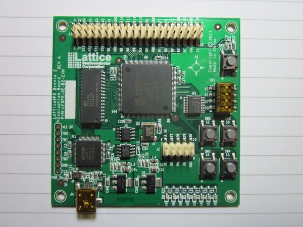
Here's the board I settled on in the end. Rather than go for Xilinx, which I've worked with in the past, I
decided to experiment with a Lattice FPGA and their toolset. I liked the look of this board because it's
quite simple, with just an XP2 series FPGA part (in the kind of package where you can see all the pins) along
with a fast SRAM and an SPI flash memory. They probably haven't brought out enough I/O pins to satisfy MK,
but there's plenty for what I want and they come out to standard 0.1" pin headers, so prototyping will be
easy. A nice feature is having the programmer on the board in the form of an FTDI chip, so no need to buy an
expensive programming cable and, as it's Lattice's own board, their development software knows how to talk to
it. A further advantage of having the FTDI part there is that the second channel can function as a UART
connection between the FPGA and the PC.
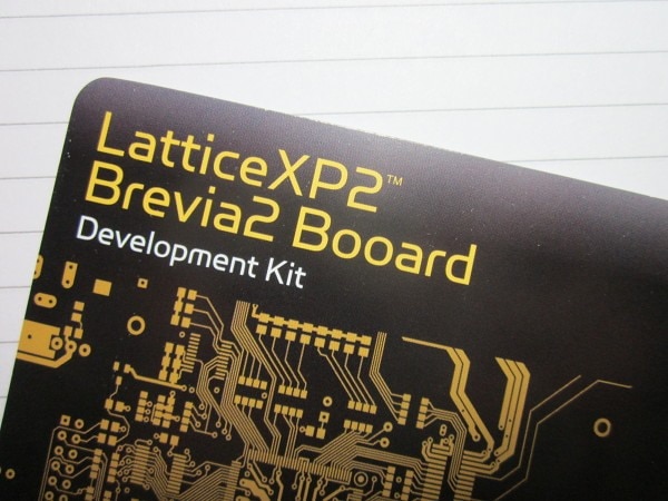
If you study the following photo carefully you may be able to spot the typo that lead to my title for this
blog (if you don't know what a Boojum is, see reference [1] below).
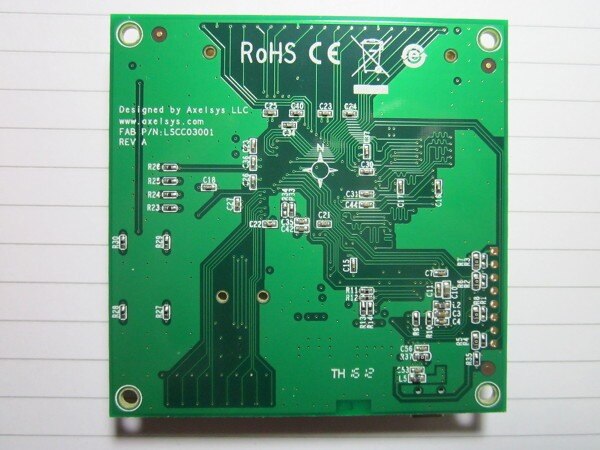
Here are photographs of top and bottom.
Product LinkProduct Link
It's a nicely made, 4-layer board, with all the appropriate decoupling, so no complaints there.
The FPGA comes preprogrammed with a soft processor (Lattice calls it the Mico8) that runs code that enables
it to present a menu to the PC and execute simple commands. So my first task was to see if I could get that
functioning before doing anything of my own.
I'd already installed Lattice's Diamond design software before purchasing the board. I did that as a safety
measure - no point buying the board if I couldn't develop with it. The design software is free, but does
require registering and setting up a user account. The software is node-locked to the MAC address of the
computer. The first time I installed it, it failed to work and I just got two pop-up boxes with unhelpful
messages before it shut down (telling you that there has been a program exception isn't really very useful).
At first I thought it might be licensing - I'd inadvertantly used the WiFi MAC address rather than the
ethernet one to get a licence file - but changing to a licence based on the ethernet didn't help, so I
uninstalled the software and reinstalled it. When I reinstalled, I accepted everything and that time it was
fine (the first time I'd gone for a cut-down install to save space).
Since I'd already installed the design software, which apparently includes drivers, I just plugged the dev
board into the PC and ignored the warnings on the packaging to install drivers first. However, regardless of
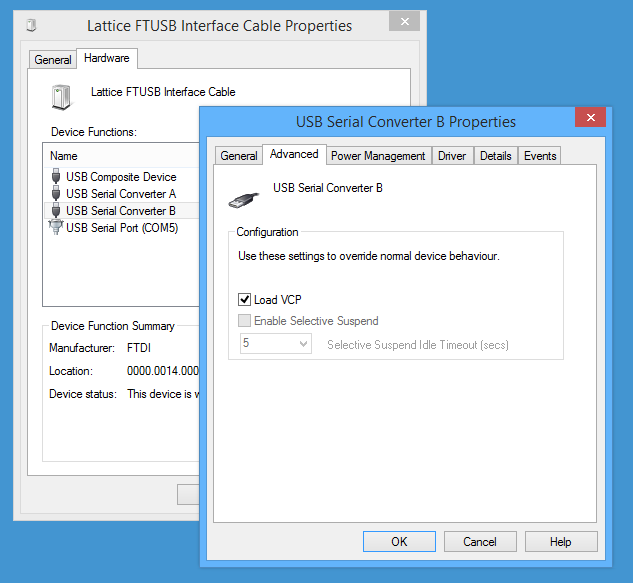
that, Windows went off and fetched a driver from somewhere. Then I was posed with a puzzle. In the Device
Manager, the board showed up under USB devices but there was no COM port so I didn't know what to enter into
pUTTY's setup. After fiddling around for a bit, I realised that the properties for the B channel had a tick
box for VCP (virtual COM port), I ticked that, that gave me the COM port but without a port number, I pulled
the USB and reinserted it, and finally had COM5 that I could enter into the properties on the serial set-up
of pUTTY (a bit painful, but that's computers for you).
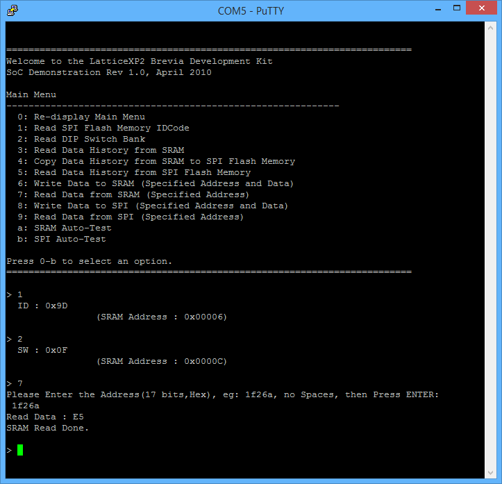
When I pressed the reset on the board I saw this on the terminal. You can see I've issued a couple of
commands and the replies that came back. So I seem to have a working board that can talk to the PC.
Next task will be to see if I can get a little, simple VHDL synthesised and on to the board - maybe count on
the LEDs, or something like that. Then I'll have a go at doing a real project (probably something music
related, as that seems like an interesting area to explore and should be a nice fit with the FPGA's
capabilities).
The next part is here
Booards and Boojums: Lattice XP2 Brevia2 Board: Part 2: Count Those LEDs!
Top Comments