


Over on another thread
https://www.element14.com/community/thread/55738/l/bc184l-transistor-component
a question was asked relating to the Power Boost, a guitar effects pedal from the past that the poster is in the process of recreating
(the question was about pcb design and so is irrelevant to my interest here).
When I looked at the circuit there were several things that I was immediately curious about, so I had a go at simulating
it to get some answers. Below are the questions I asked myself and the answers that came from the simulation. (Note that
this isn't a tutorial and I'm not trying to teach with it. It's an exploration of something that interests me and,
hopefully, may interest you too. I'd welcome comments, particularly if anyone wants to tell me about things I'm getting
wrong.)
Firstly, here's the circuit as I simulated it.
What is the effect that the circuit produces?
First thing to notice is that the overall circuit has been built from two distinct parts. If we wanted to, we could
separate them at C5, the capacitor that couples the signal from one to the other, and if we did we'd have two individual
circuits that would each work perfectly well by itself. The first section, comprised of transistors T1 and T2, forms an
amplifier. The second section, transistor T3, is a tone control. An interesting question here is, how did I know that
and the answer is that it's because I've seen similar circuit shapes before. The amplifier is two gain stages with
feedback from the collector of T2 to the emitter of T1. The tone control is famous. It was first published by Baxandall
in 1952 in the British magazine Wireless World (his circuit used a valve [vacuum tube] rather than a transistor), and it
must be one of the most recognisable circuits ever.
As it stands, an amplifier and a tone control would make for a rather boring guitar effect. The thing that makes it
interesting, sonically, is that the gain can be quite quickly adjusted to the point where the signal clips on the supply
rail. That adds lots of harmonics to what comes from the guitar and the overall spectrum can then be shaped by the tone
control in a similar way to a synthesizer generating a harmonically rich waveform and then manipulating it. Indeed,
wound right up, there might even be enough gain to clip top and bottom of the signal and turn it into a square wave
which, presumably, sounds really grungy [although the simulator is good on electrical matters, it doesn't tell me
anything about how signals sound].
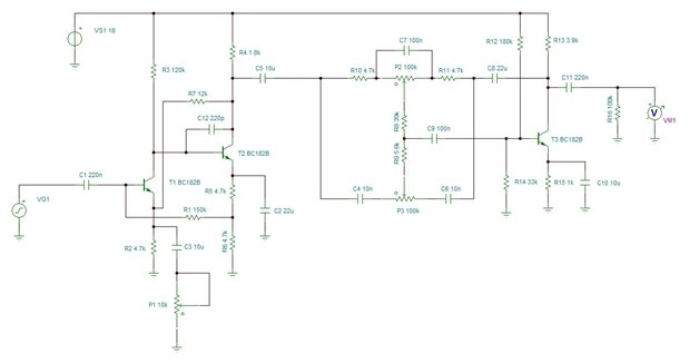
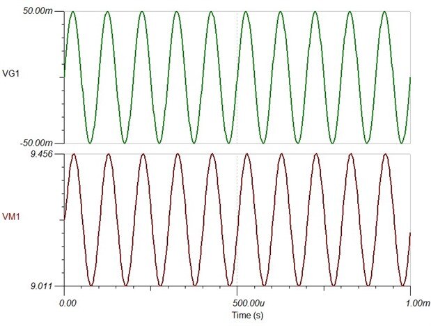
Here is the output [of the amplifier section] with a smallish signal level and the 'volume' control low
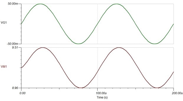
Here it is with a middling setting, where the signal is nicely clipping
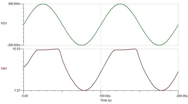
And here it is wound right up, to a point that the actual unit might not manage [I don't know what typical signal levels
are for a guitar]. Topped and tailed and a mess in between - ugh, looks horrible, guitarists probably love it.
Isn't the input capacitor a little on the small side?
The input capacitor is a coupling capacitor. It is there to pass the signal whilst blocking DC - you can have different
voltage levels on either side, but the AC signal passes through the capacitor. If you look at a book that teaches Hi-Fi
preamp design, you'll generally see a capacitor of 10uF or so in this position at the input of a preamplifier in order to pass the lower
frequencies and to ensure a response all the way down to 20Hz. To see what's happening, let's first simulate a much
simpler circuit - a coupling capacitor and a load resistor.
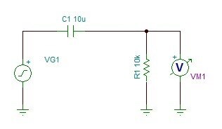
Here's the Hi-Fi case, with a 10uF capacitor and a 10k load resistor. The response is quite flat by the time we get to
20Hz:

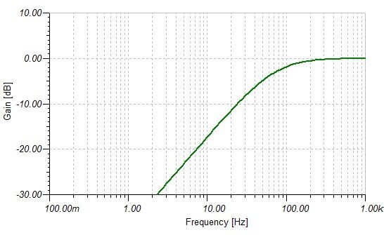
Now I'm going to drop the capacitor to the value in the Power Boost, 220nF. As you can see, the response isn't flat now
until we reach several hundred hertz:
And finally I'm going to increase the load resistor value to 150k and see what happens:
It should be evident that the response depends on both the capacitor and the resistance (which is really the input
impedance of the amplifier - it doesn't have to be a simple resistor, though it often is in a Hi-Fi system where it's
common to find a 10k volume control immediately following the input capacitor). Together they form a high-pass filter.
If we increase the input impedance, we can decrease the capacitor value and leave the response the same. And that's
what's happening here. The amplifier has a much higher input impedance than the line-in on an amplifier would have, so
the capacitor can be smaller. It's evident that the designers weren't so fussy as hi-fi designers - the response only
just manages 20Hz, and might not manage that given the large tolerance on capacitor values - but for a guitar effects
unit they didn't need to be perfectionist about it.
What is the input impedance?
Following on from the last question, how did I know what the input impedance was? Easy, I just read the value of R1. For
AC, looking into the base of T1, we have a 150k resistor in series with two 4k7 resistors in parallel [to AC, the top of
R5 is no different to ground]. That's a bit over 150k. That's then in parallel with whatever load the transistor base
presents. The transistor is working as a follower and so we might expect it to be approximately the emitter resistance
times the beta of the transistor (which would be much higher than the 150k, unless the volume control was well up) but
the emitter resistance is also being driven by the output which is working to try and keep the emitter voltage a Vbe
drop below the base voltage. That means it is much less of a load on the transistor than we might think and the load of
the base will be less too. All in all, it's roughly the resistor value.
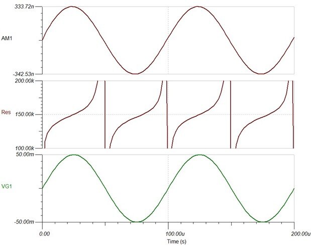
Here it is simulated. It's nominally 150k, though it moves around in response to the signal (I think that's down to the
feedback circuit and the way it has to have an error term to drive it, but this blog will never end if I wander down
that path, so I'll leave it there for now).
How can we calculate what the gain of the amplifier is?
On the face of it, this seems to be a very complicated question, but it's actually much simpler than it might first
appear. The reason for that is the negative feedback. We don't need to work out the gains of the individual stages and
multiply them together, instead, provided that the two stages have plenty of gain, which they do, the overall gain is
largly defined by the feedback components and is simply the inverse of the attenuation that the feedback provides. It
won't be exact - this isn't a precision op-amp - but it will be close. Importantly, for an item that is to be
manufactured, the circuit removes much of the variability of the transistor parameters and gives a device that will
perform consistently.
With the volume control set to 10k, the emitter resistance (as far as ac is concerned) is the 4k7 in parallel with the
10k
(10k x 4k7) / (10k + 4k7) = 3.197k
The gain will be
(12k + 3.197k) / (3.197k) = 4.75
Here's a simulation with a 100mV pk/pk input and the volume pot set to 10k. The output is taken from C5. The simulated
gain is 4.45, which is reasonably close to my simple calculation.
That's the minimum gain. The gain increases as the pot resistance decreases.
Here are the calculated values of gain for different volume control settings
10k 4.75
9k 4.89
8k 5.05
7k 5.23
6k 5.55
5k 5.95
4k 6.55
3k 7.55
2k 9.55
1k 15.54
500 25
200 61
100 121
50 241
20 600
It gets a bit silly towards the end and my calculated values are probably diverging quite quickly from the reality of
the circuit. The poster reported that people used log pots reverse wired and you can see why from these figures.
What is the role of capacitor C12?
To see what the capacitor does, let's first look at the frequency response of the amplifier without the capacitor being
present. This is the frequency response as far as the output of C5; I haven't included the tone control stage.
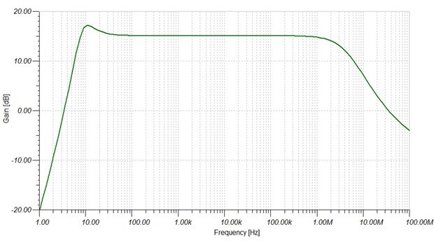
What's immediately apparent is how impressive the amplifier is. It doesn't start to roll off until it gets to 2 or 3MHz,
there is gain there [0dB is a gain of 1] up to about 25MHz, and the gain is nice and flat in the passband. All that from
two simple transistors.
Now here's the response with the capacitor in place.
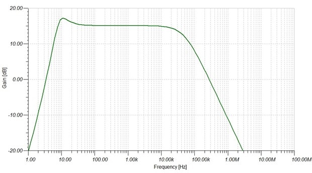
This time we can see that the response is rolling off from just above 20kHz and the gain is down to unity between 200
and 300kHz.
Why did the designer do that?
The input is a high impedance and will pick up signals well; the overall response extends up into the shortwave radio
area; and when the circuit is clipping it will rectify (which is a way of demodulating amplitude-modulated signals like
those transmitted in the Medium Wave band). So one reason was probably to reduce its susceptability to radio
interference.
The other reason for rolling off gain like this is that it helps to reduce the possibility of spurious oscillation at
higher frequencies.
What does the frequency response of the tone control look like?
Here's a composite of the five cases: both controls 50%, treble boost, treble cut, bass boost and bass cut. (I didn't
know how to do that in the simulator, so I ran it for each case and than used a paint package to merge them.)
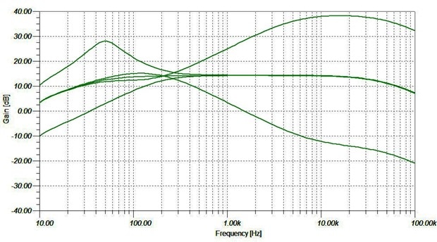
The treble control works from 200Hz upwards, the bass from 400Hz downwards. The treble is fine - it slopes off above
20kHz, but we don't care about that since it's beyond our ability to hear. The bass is less good on paper, sloping down
below 50Hz, though that is probably not of much concern to a guitarist. The changeover point is lower than what you'd see
with a Hi-Fi amplifier - I presume it was chosen by experiment: it's probably what worked well on the prototype and
sounded good.
Top Comments