element14 Community
element14 Community
    Register Log In
  • Site
  • Search
  • Log In Register
  • Members
    Members
    • Benefits of Membership
    • Achievement Levels
    • Members Area
    • Personal Blogs
    • Feedback and Support
    • What's New on element14
  • Learn
    Learn
    • Learning Center
    • eBooks
    • STEM Academy
    • Webinars, Training and Events
    • Learning Groups
  • Technologies
    Technologies
    • 3D Printing
    • Experts & Guidance
    • FPGA
    • Industrial Automation
    • Internet of Things
    • Power & Energy
    • Sensors
    • Technology Groups
  • Challenges & Projects
    Challenges & Projects
    • Design Challenges
    • element14 presents
    • Project14
    • Arduino Projects
    • Raspberry Pi Projects
    • Project Groups
  • Products
    Products
    • Arduino
    • Dev Tools
    • Manufacturers
    • Raspberry Pi
    • RoadTests & Reviews
    • Avnet Boards Community
    • Product Groups
  • Store
    Store
    • Visit Your Store
    • 'Choose another store...'
      • Europe
      •  Austria (German)
      •  Belgium (Dutch, French)
      •  Bulgaria (Bulgarian)
      •  Czech Republic (Czech)
      •  Denmark (Danish)
      •  Estonia (Estonian)
      •  Finland (Finnish)
      •  France (French)
      •  Germany (German)
      •  Hungary (Hungarian)
      •  Ireland
      •  Israel
      •  Italy (Italian)
      •  Latvia (Latvian)
      •  
      •  Lithuania (Lithuanian)
      •  Netherlands (Dutch)
      •  Norway (Norwegian)
      •  Poland (Polish)
      •  Portugal (Portuguese)
      •  Romania (Romanian)
      •  Russia (Russian)
      •  Slovakia (Slovak)
      •  Slovenia (Slovenian)
      •  Spain (Spanish)
      •  Sweden (Swedish)
      •  Switzerland(German, French)
      •  Turkey (Turkish)
      •  United Kingdom
      • Asia Pacific
      •  Australia
      •  China
      •  Hong Kong
      •  India
      •  Korea (Korean)
      •  Malaysia
      •  New Zealand
      •  Philippines
      •  Singapore
      •  Taiwan
      •  Thailand (Thai)
      • Americas
      •  Brazil (Portuguese)
      •  Canada
      •  Mexico (Spanish)
      •  United States
      Can't find the country/region you're looking for? Visit our export site or find a local distributor.
  • Translate
  • Profile
Personal Blogs
  • Members
  • More
Personal Blogs
Legacy Personal Blogs Call That a Relay?
  • Blog
  • Documents
  • Mentions
  • Sub-Groups
  • Tags
  • More
  • Cancel
  • New
Blog Post Actions
  • Subscribe by email
  • More
  • Cancel
  • Share
  • Subscribe by email
  • More
  • Cancel
Group Actions
  • Group RSS
  • More
  • Cancel
Engagement
  • Author Author: Andrew J
  • Date Created: 3 Mar 2020 9:32 AM Date Created
  • Views 956 views
  • Likes 15 likes
  • Comments 9 comments
Related
Recommended

Call That a Relay?

Andrew J
Andrew J
3 Mar 2020

This isn't meant to be an educational posting where you will learn a bunch of stuff about relays, but I've being doing some work recently that I thought might be of interest to some, particularly old-school engineers, to see how things change over time.


I would think we're all used to seeing modern relays that plug into breadboards and PCBs to switch signals.  I've opened one up, mostly, to see what's inside - mostly - I wanted it to still work after surgery!:


image

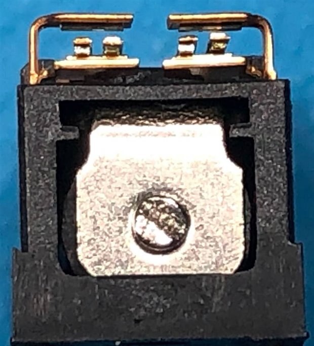
A 9V DPDT relay - you can see the contacts, which are Normally Open (NO) in the image above.

imageimage

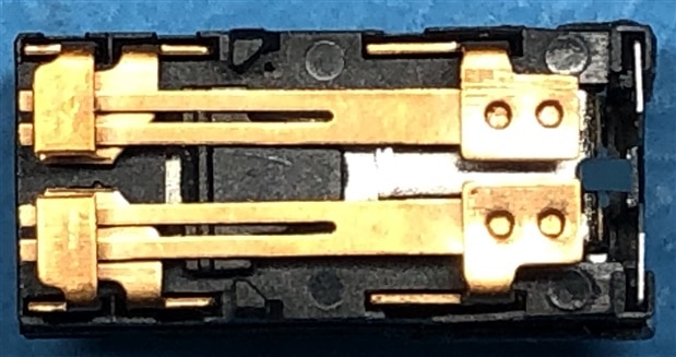
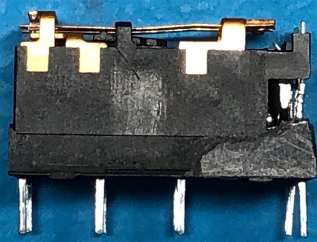
Same relay from above and side, contacts on left.  Here you can see the movable armature(contact) springs.

Not shown in the images above is the coil - that's hidden in the body.  Just as a recap of how a relay works - a voltage is applied across the coil terminals (pins on the right) which magnetises the coil itself.  That operates the armature(s) closing* the contacts and allowing a separate signal to flow through the relay terminals (3 pins on the left.)  That's a simplistic explanation but suffices.


*relays will come in different types and operate in different ways:

  • Normally Open (NO) - in the non-energised state, contacts are not made
  • Normally Closed (NC) - in the non-energised state, contacts are made
  • Changeover - when energised, contacts switch from one position to an alternate position
  • Make before Break - when energised, one set of contacts switch from one position to an alternate position THEN the contact which is carrying a signal will open, transferring the signal to the made contact
  • Break before Make - when energised, the set of contacts that is carrying the signal open THEN a separate contact will close and pick up the signal.


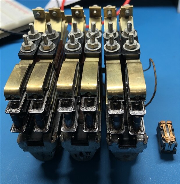
So we're in a world of miniature relays but in the words of Crocodile Dundee: "Call that a relay?  That's not a relay.  THIS is a relay"

image

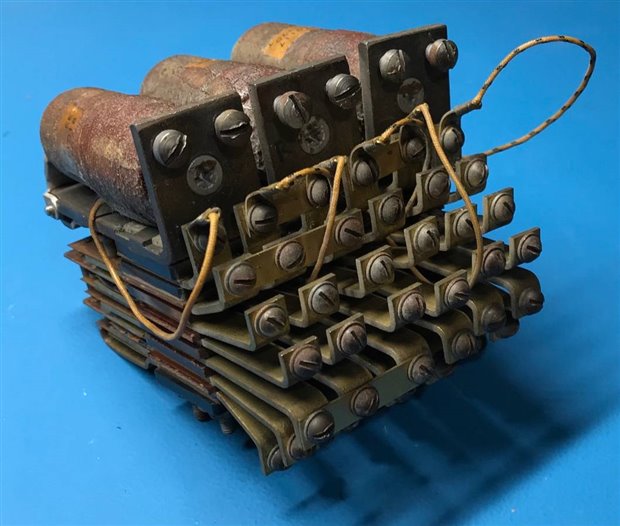
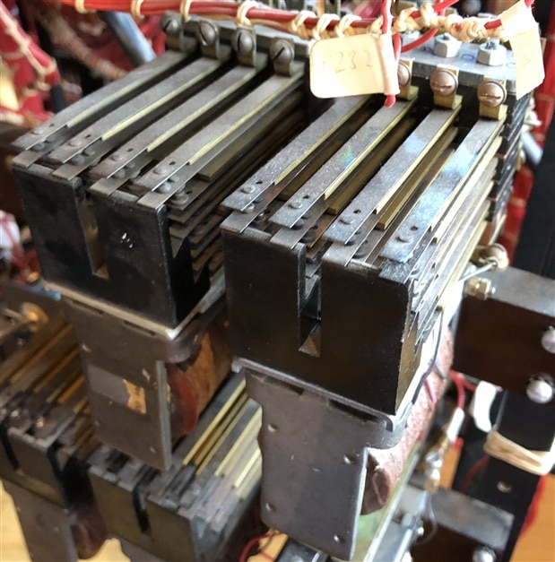
The image above is a British Tabulating Machine Company Ltd Type A Multi-Relay, here with the coils and contact spring terminals visible.  There was no, one, configuration for a Type A relay - they were built up from a parts bin into the configuration required and BTM used them for the punch card machines they built.  Here, we see a relay that we (the Bombe rebuild team) use on the Bombe for indicating letters in the machine's Indicator Unit - BTM were responsible for the design and build of the Bombe under the codename CANTAB and chief engineer Harold 'Doc' Keen.


Firstly, I need to point out that the Type A relay as seen above was not used on WW2 Bombes, we've had to use 5 of these because we can't find enough of the Multi Relays that were actually used on the Bombe:

imageimage

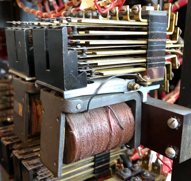
As you can imagine, getting hold of any parts that are 80 years or so old isn't easy but we can, and have, built up alternatives that whilst still maybe 50 - 60 years old are more findable.  The images above show that similar mechanisms to small, modern relays are used, just on a different scale.  The coil, under the yoke, is energised creating a magnetic field that pulls in the armature at the front of the coil, which is hinged and lifts the armature (contact) springs in the relay pile up above the yoke.  This relay consists of two pile ups with a mix of changeover and break before make contacts.


Back to the Type A relay unit which is in a bit of a sorry state, but it's had a hard life before we got our hands on it, and I've removed it from the machine to clean up as far as possible.  It consists of 3 coils and 3 pairs of Relay Pile Ups (6 Pile Ups altogether) used to indicate one of 12 letters on the machine's indicator unit - really it's 3 linked Type A relays, you should be able to see the shorting bars on some of the contact spring terminals.  On the Bombe itself we have 5 sets of these plus 2 of the contemporary 'correct' multi relays that can indicate one or more of 26 letters across 3 Chains.  I'm aware I'm using terminology from the Bombe here but basically:

  • The Bombe is running through a set of checks looking for what it would call a Good Stop.
  • At a Good Stop it stops running and, amongst a host of other things that happen, a contact is made on the appropriate indicator relay to flag a letter (typically, but could be more than one) in an Indicator Unit which consists of 3 lots of 26 letters.
  • The Bombe can check 3 different set ups simultaneously each of which is termed a 'Chain'.
  • Each Chain corresponds to one of the 3 groups in the indicator unit so that the operator knows which Chain has found the good stop.


That's it for the Bombe and contextualising the relay.  As I say, I'm taking this apart to clean it - there's lots of gunk and rust in the mechanism and it is way, way out of operating spec.  Normally I would use an electrolysis bath to clean up the steel parts but as it is the first time I've done this I wanted to be a lot more hands on and get a feel for the parts and the operation.  This time then, I'm using very fine steel wool, cleaning paste, IPA and more patience than is right for any one person to possess - to give you an idea, it has taken about 45 - 50 hours to clean the whole lot.  Here's a comparison and a good photo of one of the pile ups:

image

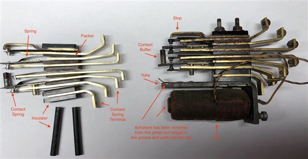
Anyone who knows anything about these things can see immediately how far out of adjustment it must be (also, how dirty it is.)  There's quite a few parts in each relay pile up and below is an exploded view of just one of the 3 relay units:

image

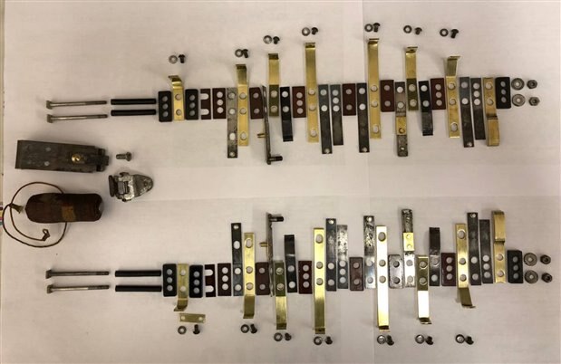
Here it is cleaned and re-assembled:

imageimage

A lot cleaner but still out of spec.  As a comparison of size:

image


Of course, there are bigger relays used in industry than we use on PCBs and breadboards but the Type A relay was in common use until at least the 1960s (as far as I can tell!)


What this thing needs now is adjusting and testing but I don't have the tools to hand and need to wait until April to get going on that.  If anyone's interested I'll follow up with information on that process seperately.

  • Sign in to reply

Top Comments

  • jw0752
    jw0752 over 3 years ago +7
    Hi Andrew, Thanks for the interesting post. Personally I love relays. I have several hundred that I have salvaged over the years and frequently use them in my projects. Sometimes there is no substitute…
  • Andrew J
    Andrew J over 3 years ago in reply to jw0752 +5
    Glad you found it interesting John. It's certainly something to see the relays operating whilst the Bombe is running - there's something very rhythmic about the noise the machine makes when it runs. It…
  • genebren
    genebren over 3 years ago +2
    Interesting blog! I really enjoy looking back in the history of electricity/electronics. It is amazing to think back to when they needed to build so much of this from scratch as they did not a robust network…
  • dubbie
    dubbie over 3 years ago in reply to Andrew J

    Andrew,


    The only mainframe I cam remember using was a Norsk Data one. It might have been a good computer but the reliability was appalling. If it ran throughout a 2 hour lab without failing we considered it a success. This was the days before PCs so there was no alternative.


    Dubbie

    • Cancel
    • Vote Up +2 Vote Down
    • Sign in to reply
    • More
    • Cancel
  • Andrew J
    Andrew J over 3 years ago in reply to dubbie

    image


    The first place I worked, SD-Scicon, had a social club on site, and they didn't mind it being used at lunchtimes.  That could be fatal for afternoon productivity, but I do recall it being a god send when I was stuck on a 5-day IBM Mainframe course.  Man, that was dire.

    • Cancel
    • Vote Up +2 Vote Down
    • Sign in to reply
    • More
    • Cancel
  • dubbie
    dubbie over 3 years ago in reply to Andrew J

    I must have been there just at the final development stage of system X as at another placement in the main GEC Factory in Coventry all us 'graduate apprentices' were given the task of getting the development model of a System X exchange working. But we knew pretty much nothing so it was completely beyond us. I think they just gave it to us to play with to keep us quiet and out of their way. There were a number of such 'important' tasks that apprentices had to do, like checking there were enough toilets for the factory and writing a report about it.


    Still, it wasn't all bad as it was in the days when large factories used to have social clubs on site, with a bar and everything, effectively a working man's club. We were paid in cash on a Friday afternoon as I remember and we (graduate apprentices) all started going to the club to play snooker and drink (lemonade obviously - no coca cola in clubs in those days) before and after collecting our pay. Nobody in the factory really cared as we were just a nuisance as far as I can tell/remember. We were caught out when the apprentice manager who was there to supervisor the distribution of our pay, wondered why individual apprentices keep appearing, collecting pay and then disappearing again, as previously we tended to all gaggle together. He followed one of us back to the club and that was the end of that perk.


    Dubbie

    • Cancel
    • Vote Up +2 Vote Down
    • Sign in to reply
    • More
    • Cancel
  • Andrew J
    Andrew J over 3 years ago in reply to dubbie

    It was a bit before my time really - I wasn't in work - but from what my wife says, things went digital at BT during the 1980s.  She was involved in projects to rip out Strauger exchanges and replace them with a small digital box tucked in the corner of the massive warehouse that then became available!  From my perspective now, it's disappointing that a lot of the parts just got skipped.  It's even hard to get hold of relay adjusting tools.

    • Cancel
    • Vote Up +2 Vote Down
    • Sign in to reply
    • More
    • Cancel
  • dubbie
    dubbie over 3 years ago

    One of my first placements during my degree was at a GEC Relay factory in Coventry, which was the mid or late-70's I think. These were of the type used in telephone exchanges. I cannot tell you much about them as they were closing down the production line I think as everything was about to go digital (System X?).


    Dubbie

    • Cancel
    • Vote Up +2 Vote Down
    • Sign in to reply
    • More
    • Cancel
>
element14 Community

element14 is the first online community specifically for engineers. Connect with your peers and get expert answers to your questions.

  • Members
  • Learn
  • Technologies
  • Challenges & Projects
  • Products
  • Store
  • About Us
  • Feedback & Support
  • FAQs
  • Terms of Use
  • Privacy Policy
  • Legal and Copyright Notices
  • Sitemap
  • Cookies

An Avnet Company © 2023 Premier Farnell Limited. All Rights Reserved.

Premier Farnell Ltd, registered in England and Wales (no 00876412), registered office: Farnell House, Forge Lane, Leeds LS12 2NE.

ICP 备案号 10220084.

Follow element14

  • X
  • Facebook
  • linkedin
  • YouTube