element14 Community
element14 Community
    Register Log In
  • Site
  • Search
  • Log In Register
  • Community Hub
    Community Hub
    • What's New on element14
    • Feedback and Support
    • Benefits of Membership
    • Personal Blogs
    • Members Area
    • Achievement Levels
  • Learn
    Learn
    • Ask an Expert
    • eBooks
    • element14 presents
    • Learning Center
    • Tech Spotlight
    • STEM Academy
    • Webinars, Training and Events
    • Learning Groups
  • Technologies
    Technologies
    • 3D Printing
    • FPGA
    • Industrial Automation
    • Internet of Things
    • Power & Energy
    • Sensors
    • Technology Groups
  • Challenges & Projects
    Challenges & Projects
    • Design Challenges
    • element14 presents Projects
    • Project14
    • Arduino Projects
    • Raspberry Pi Projects
    • Project Groups
  • Products
    Products
    • Arduino
    • Avnet & Tria Boards Community
    • Dev Tools
    • Manufacturers
    • Multicomp Pro
    • Product Groups
    • Raspberry Pi
    • RoadTests & Reviews
  • About Us
  • Store
    Store
    • Visit Your Store
    • Choose another store...
      • Europe
      •  Austria (German)
      •  Belgium (Dutch, French)
      •  Bulgaria (Bulgarian)
      •  Czech Republic (Czech)
      •  Denmark (Danish)
      •  Estonia (Estonian)
      •  Finland (Finnish)
      •  France (French)
      •  Germany (German)
      •  Hungary (Hungarian)
      •  Ireland
      •  Israel
      •  Italy (Italian)
      •  Latvia (Latvian)
      •  
      •  Lithuania (Lithuanian)
      •  Netherlands (Dutch)
      •  Norway (Norwegian)
      •  Poland (Polish)
      •  Portugal (Portuguese)
      •  Romania (Romanian)
      •  Russia (Russian)
      •  Slovakia (Slovak)
      •  Slovenia (Slovenian)
      •  Spain (Spanish)
      •  Sweden (Swedish)
      •  Switzerland(German, French)
      •  Turkey (Turkish)
      •  United Kingdom
      • Asia Pacific
      •  Australia
      •  China
      •  Hong Kong
      •  India
      • Japan
      •  Korea (Korean)
      •  Malaysia
      •  New Zealand
      •  Philippines
      •  Singapore
      •  Taiwan
      •  Thailand (Thai)
      • Vietnam
      • Americas
      •  Brazil (Portuguese)
      •  Canada
      •  Mexico (Spanish)
      •  United States
      Can't find the country/region you're looking for? Visit our export site or find a local distributor.
  • Translate
  • Profile
  • Settings
Personal Blogs
  • Community Hub
  • More
Personal Blogs
Legacy Personal Blogs Control Logic
  • Blog
  • Documents
  • Mentions
  • Sub-Groups
  • Tags
  • More
  • Cancel
  • New
  • Share
  • More
  • Cancel
Group Actions
  • Group RSS
  • More
  • Cancel
Engagement
  • Author Author: timswift
  • Date Created: 1 May 2017 6:11 PM Date Created
  • Views 629 views
  • Likes 3 likes
  • Comments 1 comment
  • logic
  • transistor
  • control logic
  • counter
  • cpu
  • 8 bit computer
Related
Recommended

Control Logic

timswift
timswift
1 May 2017

I have now finished all ten 4 bit register boards and with them about one third of the soldering (I hope so at least).

So now I am moving on to the construction of the multiplexers but in the meantime I thought I might look into the design of the control logic (a subject I have avoided until now).

My first thought was to use a EEPROM and a 4 bit register along with a clock to drive the register but this did not seem quite right on a transistor computer so I found a alternative;


To keep things small (relatively small) I am limiting my opcode to 4 bits if I want more instructions I can always remove the control board and replace it with the before mentioned EEPROM.


to help remove confusion I will give a explanation of the CPU's timing;

rd means data is taken from the bus and placed in a register and rt means a mux takes data from a register and puts it on a bus.

All registers in the computer are transparent the T (temporary) reg acts to prevent cycling and oscillation.

The T-cycle for T rd and C rd is one half a clock cycle (T rd is high while the clock is high and C rd while the clock is low) and one clock cycle for the rest of the control signals doing this allows for a mux to select a source and place the data in the T reg in one cycle the next cycle is used to rd the data into a destination (the second cycle is only necessary if source equals destination).

The fetch takes six clock ticks;


1: load data at address PC into IR

2: add one to PC result in T

3: PC read

4: load data at address PC into B

5: add one to PC result in T

6: PC read

7: begin to execute instruction


Here is the most up-to-date block diagram of the main data path;

image

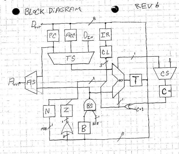
As you may see this is very different from the diagram in the last post but while inspecting it after three months I found many errors and simplifications.


This is the current instruction set but I may very well change this;


  • constant to ACC (Is this really necessary?)
  • memory to ACC
  • ACC to memory


  • jump
  • jump if zero
  • jump if negitive
  • jump if carry set


  • set carry
  • clear carry
  • add with carry
  • subtract with carry
  • and
  • or
  • xor
  • shift right


  • halt program (program is resumed when user presses a button)


And now after this brief explanation a diagram of the control logic;

image

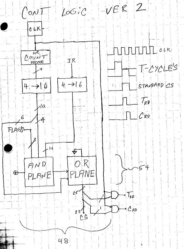
On the AND-plane a given output is high if all inputs for that output are high conversely, on the or plane if one input goes high the all corresponding outputs go high.

The AND gates are to shorten the T rd and C rd signals.

The AND-OR plane will be constructed from diodes and will be approximately five inches wide and six long.

I estimate 100 transistors for the counter, 60 for each decoder, and a dozen or two for the clock and gates this comes to about 220 transistors total bringing the count of the entire computer under 1000.

The counter will be constructed like this;

image

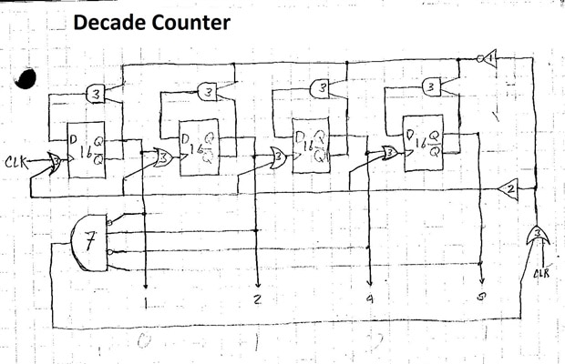
The clear input is necessary on start up. All FF are edge triggered.


Tim

  • Sign in to reply
  • DAB
    DAB over 8 years ago

    Your post brings back memories of my computer architecture classes back in the 1970's.


    Yes, there is a good use for the constant into the ACC option.

    It is very useful when you need to cycle through data entries using fixed offsets.


    DAB

    • Cancel
    • Vote Up 0 Vote Down
    • Sign in to reply
    • More
    • Cancel
element14 Community

element14 is the first online community specifically for engineers. Connect with your peers and get expert answers to your questions.

  • Members
  • Learn
  • Technologies
  • Challenges & Projects
  • Products
  • Store
  • About Us
  • Feedback & Support
  • FAQs
  • Terms of Use
  • Privacy Policy
  • Legal and Copyright Notices
  • Sitemap
  • Cookies

An Avnet Company © 2025 Premier Farnell Limited. All Rights Reserved.

Premier Farnell Ltd, registered in England and Wales (no 00876412), registered office: Farnell House, Forge Lane, Leeds LS12 2NE.

ICP 备案号 10220084.

Follow element14

  • X
  • Facebook
  • linkedin
  • YouTube