


LED’s have always been a staple component in programming microcontrollers, they are most commonly used as indicators that elements of a program are functioning correctly. However, more people are realising that high powered LED’s have a multitude of uses beyond the simple applications of their lower powered brethren. In this article we show you how to design your circuit to utilise these functional devices.
A very simple way of determining if a microcontroller is behaving correctly is through the use of LEDs. This could take the form of a simple “on light” to let you know there is power going to the device through to displaying binary numbers to indicate traffic on a communications bus. High power LEDs are now becoming more and more popular in embedded systems with prices falling as a result.
Here are a number of simple applications that could be created simply by using high power LEDs combined with a bit of ingenuity.
- Multicolour lamp
- Hi-power spotlight
- Portable camping light
- Propeller clock
- PC/ Car illuminations
- Hydroponics grow systems
So to get started with using these high-power LEDs you first have to work out exactly what the LEDs need to be able to do.
- Do the LEDs need to be a single colour or multicolour?
- Do the LEDs all need to be the same brightness or should they be individually controllable?
- Do the LEDs need to dim or are they constantly on?
- What power source am I going to use to drive the LEDs?
Firstly I am going to show you how to design a circuit to allow you to control the LED up to its full potential brightness without risking damage. Consider this device from rapid electronics, It is a Red LED capable of generating 20,000mCD with product code 55-2476. Looking at the device datasheet we can tell that the absolute maximum values for forward current are 50mA and forward voltage are 2.6V. It is best not to push the LED too far so maybe drop one of the values slightly to allow the LED a bit of tolerance. For this particular LED I will drop the forward voltage to 2.5V.
We can now use an LED wizard to design our circuit, such as this. For this test circuit I am going to make a portable LED light. For this I would use a 12V lead acid battery to allow me to produce a long lasting bright light. So I put the following details into the calculator.
- Source voltage – 12
- Diode Forward Voltage – 2.5
- Diode forward current (mA) – 50
- Number of LEDs – 4
This generates a basic schematic to allow me to drive the LEDs at full brightness. Note that in this configuration all of the LEDs are tied together so only one control line is required. In other configurations it is best to remember that the resistor will always make your circuit less efficient so the more LEDs you can combine into a single channel the more efficient your circuit will be.
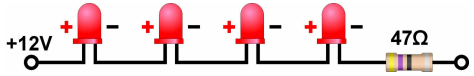
The LED wizard also tells me the current that the circuit is going to draw so I can calculate a rough estimate of how long my battery will last when powering the circuit. My battery is a 7.5Ah battery and my LED circuit consumes 50mA making for a maximum life expectancy getting on for 150 hours (7.5 / 0.05 = 150). Not bad for a luminous intensity of approx 80,000mCD (4 x 20,000mCD).
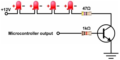
To control the LEDs you can either use an onboard PWM peripheral or for more channels use a timer interrupt software driven PWM method. The image below shows a transistor connected to the microcontroller output, allowing us to switch the LEDs on/ off from our program. Only when we activate the microcontroller output will the transistor switch on, allowing current to flow, and thus switching the LEDs on.
Here is another example using the same LEDs but in a single configuration. Notice that the supply voltage has been changed to better suit the configuration of the LEDs (6V). We are now pulling 200mA through the circuit due to the increase in the number of resistors, however we also have much more control over the LEDs as we can control each pair of LEDs separately. Our battery has 7.5Ah, therefore when we divide this by 200mA we calculate a life expectancy of 37.5 hours, still fairly impressive for a luminous intensity of up to 160,000mCD.

The above calculation would translate into a circuit like this, requiring 4 microcontroller outputs, similar to the previous example, but allows us to turn each of the 4 branches individually from 4 microcontroller outputs;
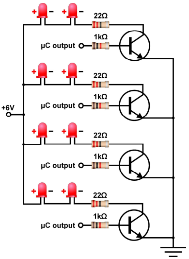
As this circuit uses four output channels, the PWM peripheral onboard the chip is not going to be much use.
Therefore we have created an example demonstrating how to get around this. We need to use the software approach of creating the brightness control signal. To allow the software approach to work at low speeds such as 4MHz without flicker, I have reduced the scale of the PWM from 0-255 to 0-63. This allows for a good flexibility of control at low speed without flicker. At a faster clock speed a larger resolution of control can be achieved without flicker.
To calculate the refresh period of the LED you would use the following equation.
( ( Clock speed / 4 ) / Timer_Period ) / Resolution = Refresh rate (Hz).
Which works out as follows.
( ( 4MHz / 4 ) / 256 ) / 64 = 61Hz refresh rate.
Have a look through the provided flowchart here, and see if you can understand how we have made a software controlled PWM component.
We’ve reached the end of this article. Hopefully you have an insight into how to maximise the LEDs in your circuit. If you have any comments, feel free to comment below.
Top Comments
-

DAB
-
Cancel
-
Vote Up
+1
Vote Down
-
-
Sign in to reply
-
More
-
Cancel
Comment-

DAB
-
Cancel
-
Vote Up
+1
Vote Down
-
-
Sign in to reply
-
More
-
Cancel
Children