element14 Community
element14 Community
    Register Log In
  • Site
  • Search
  • Log In Register
  • Community Hub
    Community Hub
    • What's New on element14
    • Feedback and Support
    • Benefits of Membership
    • Personal Blogs
    • Members Area
    • Achievement Levels
  • Learn
    Learn
    • Ask an Expert
    • eBooks
    • element14 presents
    • Learning Center
    • Tech Spotlight
    • STEM Academy
    • Webinars, Training and Events
    • Learning Groups
  • Technologies
    Technologies
    • 3D Printing
    • FPGA
    • Industrial Automation
    • Internet of Things
    • Power & Energy
    • Sensors
    • Technology Groups
  • Challenges & Projects
    Challenges & Projects
    • Design Challenges
    • element14 presents Projects
    • Project14
    • Arduino Projects
    • Raspberry Pi Projects
    • Project Groups
  • Products
    Products
    • Arduino
    • Avnet Boards Community
    • Dev Tools
    • Manufacturers
    • Multicomp Pro
    • Product Groups
    • Raspberry Pi
    • RoadTests & Reviews
  • Store
    Store
    • Visit Your Store
    • Choose another store...
      • Europe
      •  Austria (German)
      •  Belgium (Dutch, French)
      •  Bulgaria (Bulgarian)
      •  Czech Republic (Czech)
      •  Denmark (Danish)
      •  Estonia (Estonian)
      •  Finland (Finnish)
      •  France (French)
      •  Germany (German)
      •  Hungary (Hungarian)
      •  Ireland
      •  Israel
      •  Italy (Italian)
      •  Latvia (Latvian)
      •  
      •  Lithuania (Lithuanian)
      •  Netherlands (Dutch)
      •  Norway (Norwegian)
      •  Poland (Polish)
      •  Portugal (Portuguese)
      •  Romania (Romanian)
      •  Russia (Russian)
      •  Slovakia (Slovak)
      •  Slovenia (Slovenian)
      •  Spain (Spanish)
      •  Sweden (Swedish)
      •  Switzerland(German, French)
      •  Turkey (Turkish)
      •  United Kingdom
      • Asia Pacific
      •  Australia
      •  China
      •  Hong Kong
      •  India
      •  Korea (Korean)
      •  Malaysia
      •  New Zealand
      •  Philippines
      •  Singapore
      •  Taiwan
      •  Thailand (Thai)
      • Americas
      •  Brazil (Portuguese)
      •  Canada
      •  Mexico (Spanish)
      •  United States
      Can't find the country/region you're looking for? Visit our export site or find a local distributor.
  • Translate
  • Profile
  • Settings
Personal Blogs
  • Community Hub
  • More
Personal Blogs
Legacy Personal Blogs CPLD Controlled Door Lock - Input Circuit
  • Blog
  • Documents
  • Mentions
  • Sub-Groups
  • Tags
  • More
  • Cancel
  • New
  • Share
  • More
  • Cancel
Group Actions
  • Group RSS
  • More
  • Cancel
Engagement
  • Author Author: oldmanraskers
  • Date Created: 25 Apr 2015 9:22 AM Date Created
  • Views 1177 views
  • Likes 1 like
  • Comments 11 comments
  • max_v_cpld
Related
Recommended

CPLD Controlled Door Lock - Input Circuit

oldmanraskers
oldmanraskers
25 Apr 2015

Input Circuit


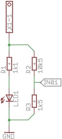
The input circuit is very simple. Consider that 24V is present at the connector X1-1; this will allow 20mA to flow through LED1 and indicate there is an input present.  Approximately 2mA will flow via R2 and R3, thereby pulling the CPLD IN01 pin to 3V (the device can accept unto 4V).


image

  • Sign in to reply

Top Comments

  • michaelkellett
    michaelkellett over 10 years ago in reply to oldmanraskers +1
    You're mixing up output drive currents and input currents. The MAXV will draw a tiny 10uA current on an input (unless you program a pullup current for that pin) so when Q1 is off you would expect to see…
  • oldmanraskers
    oldmanraskers over 10 years ago in reply to michaelkellett

    First off, thanks for your help Michael - I know I'm missing a few things here, but it's really great that you're taking the time to help out. I've never really looked at driving LEDs with so little current, I guess that will be on the agenda for today. Thanks for clearing this up image


    EDIT: I just checked the LEDs and they are still very bright - I'm a little gobsmacked image

    • Cancel
    • Vote Up 0 Vote Down
    • Sign in to reply
    • More
    • Cancel
  • michaelkellett
    michaelkellett over 10 years ago in reply to oldmanraskers

    You're mixing up output drive currents and input currents.

    The MAXV will draw a tiny 10uA current on an input (unless you program a pullup current for that pin) so when Q1 is off you would expect to see 3.3 - (4700 * 10E-6) = 3.253V which is fine.

    When Q1 is on the CPLD input will be pulled down to about 100mV (depends on the device you use for Q1)

    The nice thing about this circuit is that the LED current is independent of the input to the CPLD, so the LED current is (3.3 - LEDvolts)/R2. A reasonable bright RED LED (Farnell 1814437) will drop about 1.8V at 10mA (unless you want to light up a whole room you really do not need 20mA - 2mA will be more than enough for indication).

    So we can work out R2 = (3.3 - 1.8)/10E-3 = 150R, and for 2mA you need 750R - so my standard value of 560 wasn't too far off the mark image


    MK

    • Cancel
    • Vote Up +1 Vote Down
    • Sign in to reply
    • More
    • Cancel
  • oldmanraskers
    oldmanraskers over 10 years ago in reply to michaelkellett

    Looking at the data sheet for MAX V devices I am not sure why I have the idea that the CPLD can only tolerate 2mA at an input - the datasheet seems to indicate 25mA - does anyone have experience of these devices? IF THAT is the case then I will use the above circuit but replace the 560 ohm with 56 ohms?

    • Cancel
    • Vote Up 0 Vote Down
    • Sign in to reply
    • More
    • Cancel
  • oldmanraskers
    oldmanraskers over 10 years ago in reply to michaelkellett

    I like that idea Michael, a transistor will allow me to use the 24V inputs I need, but I'm not sure about the calculations - I need to get 20mA through the LED and only 2mA into the CPLD input - am I right in thinking that if I have a transistor collector connected to the bottom of R1 and R2, I will only get 2.5mA through the LED but 3mA into the CPLD? Would you put the LED into the base side of the transistor? I'm assuming you mean this circuit?


    image

    • Cancel
    • Vote Up 0 Vote Down
    • Sign in to reply
    • More
    • Cancel
  • michaelkellett
    michaelkellett over 10 years ago

    I think I would do it like this:


    image


    Much less power wasted in the LED resistor and the input to the CPLD goes from low impedance 0V when button pressed to pull up to its own 3.3V supply. It will be less susceptible to noise and variations in the resistor values.


    If you will have long wires to the button something else might be needed.


    If you want to detect a 24V (or other voltage) signal then replace the button with an NPN transistor with a resistor from base to ground and an input resistor to the base, collector to R1 and R2, emitter to ground.

    By setting the input resistor correctly you can have almost any input voltage and the CPLD input is quite well protected.

    If the electrical environment is awful then add a capacitor from the transistor base to ground.


    You'll need to debounce the signals but you can do that in logic in the CPLD.


    MK

    • Cancel
    • Vote Up 0 Vote Down
    • Sign in to reply
    • More
    • Cancel
>
element14 Community

element14 is the first online community specifically for engineers. Connect with your peers and get expert answers to your questions.

  • Members
  • Learn
  • Technologies
  • Challenges & Projects
  • Products
  • Store
  • About Us
  • Feedback & Support
  • FAQs
  • Terms of Use
  • Privacy Policy
  • Legal and Copyright Notices
  • Sitemap
  • Cookies

An Avnet Company © 2025 Premier Farnell Limited. All Rights Reserved.

Premier Farnell Ltd, registered in England and Wales (no 00876412), registered office: Farnell House, Forge Lane, Leeds LS12 2NE.

ICP 备案号 10220084.

Follow element14

  • X
  • Facebook
  • linkedin
  • YouTube