element14 Community
element14 Community
    Register Log In
  • Site
  • Search
  • Log In Register
  • Community Hub
    Community Hub
    • What's New on element14
    • Feedback and Support
    • Benefits of Membership
    • Personal Blogs
    • Members Area
    • Achievement Levels
  • Learn
    Learn
    • Ask an Expert
    • eBooks
    • element14 presents
    • Learning Center
    • Tech Spotlight
    • STEM Academy
    • Webinars, Training and Events
    • Learning Groups
  • Technologies
    Technologies
    • 3D Printing
    • FPGA
    • Industrial Automation
    • Internet of Things
    • Power & Energy
    • Sensors
    • Technology Groups
  • Challenges & Projects
    Challenges & Projects
    • Design Challenges
    • element14 presents Projects
    • Project14
    • Arduino Projects
    • Raspberry Pi Projects
    • Project Groups
  • Products
    Products
    • Arduino
    • Avnet Boards Community
    • Dev Tools
    • Manufacturers
    • Multicomp Pro
    • Product Groups
    • Raspberry Pi
    • RoadTests & Reviews
  • Store
    Store
    • Visit Your Store
    • Choose another store...
      • Europe
      •  Austria (German)
      •  Belgium (Dutch, French)
      •  Bulgaria (Bulgarian)
      •  Czech Republic (Czech)
      •  Denmark (Danish)
      •  Estonia (Estonian)
      •  Finland (Finnish)
      •  France (French)
      •  Germany (German)
      •  Hungary (Hungarian)
      •  Ireland
      •  Israel
      •  Italy (Italian)
      •  Latvia (Latvian)
      •  
      •  Lithuania (Lithuanian)
      •  Netherlands (Dutch)
      •  Norway (Norwegian)
      •  Poland (Polish)
      •  Portugal (Portuguese)
      •  Romania (Romanian)
      •  Russia (Russian)
      •  Slovakia (Slovak)
      •  Slovenia (Slovenian)
      •  Spain (Spanish)
      •  Sweden (Swedish)
      •  Switzerland(German, French)
      •  Turkey (Turkish)
      •  United Kingdom
      • Asia Pacific
      •  Australia
      •  China
      •  Hong Kong
      •  India
      •  Korea (Korean)
      •  Malaysia
      •  New Zealand
      •  Philippines
      •  Singapore
      •  Taiwan
      •  Thailand (Thai)
      • Americas
      •  Brazil (Portuguese)
      •  Canada
      •  Mexico (Spanish)
      •  United States
      Can't find the country/region you're looking for? Visit our export site or find a local distributor.
  • Translate
  • Profile
  • Settings
Personal Blogs
  • Community Hub
  • More
Personal Blogs
Legacy Personal Blogs Create a Programmable Instrument with SCPI - Part 1: Parser Library
  • Blog
  • Documents
  • Mentions
  • Sub-Groups
  • Tags
  • More
  • Cancel
  • New
  • Share
  • More
  • Cancel
Group Actions
  • Group RSS
  • More
  • Cancel
Engagement
  • Author Author: Jan Cumps
  • Date Created: 17 Sep 2016 4:50 PM Date Created
  • Views 5167 views
  • Likes 6 likes
  • Comments 7 comments
  • smart_instrument
  • gpib
  • labview
  • scpi
Related
Recommended

Create a Programmable Instrument with SCPI - Part 1: Parser Library

Jan Cumps
Jan Cumps
17 Sep 2016
For a hardware evaluation project I'm working on, I want to create a device that can be controlled via LabVIEW.
LabVIEW can talk to instruments using serial out of the box, and it knows how to talk Standard Commands for Programmable Instruments (SCPI).


image


In this blog I'm trying out the SCPI parser library of Jan Breuer.


SCPI

Standard Commands for Programmable Instruments (SCPI) is an IEEE standard for communicating with instruments.

It defines how a dialog between machines works. Like many communication languages it defines the request-reply syntax and the structure of commands and data.

A typical command that all instruments should support is the *IDN? (identity) command.

The test instrument replies with its identity. For a Rigol DS1102E oscilloscope, you'd get a reply  that looks like this: RIGOL TECHNOLOGIES,DS1102E,DS1EB104702974,00.02.01.01.00.

Other commands typically set the instrument in a certain status, change a parameter, query configuration settings or exchange data.


Because the language is standardised, there are some instrument side libraries that implement SCPI. They parse SCPI commands and help firmware developers to reply in the correct way..

I'm checking out Jan Breuer's SCPI parser library (available on github). If I manage to understand his library, I'll use it. And that's the exercise for now - getting to know the lib.


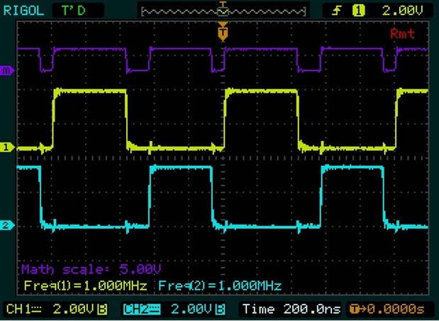
At the end of this blog series, we have a smart instrument that can control 7 PWM modules independently.

Each module will be able to generate two in-sync or complementary signals,


image


The duty cycle of each signal is separately configurable. Also the deadband is separately changeable for each signal.


Getting to know the SCPI Parser Library

My instrument will have an ARM microcontroller. But I'm first testing the library on a Windows PC.

I'm running trough the example programs to see how the commands are interpreted. My favourite learning method is stepping trough the code with a debugger.


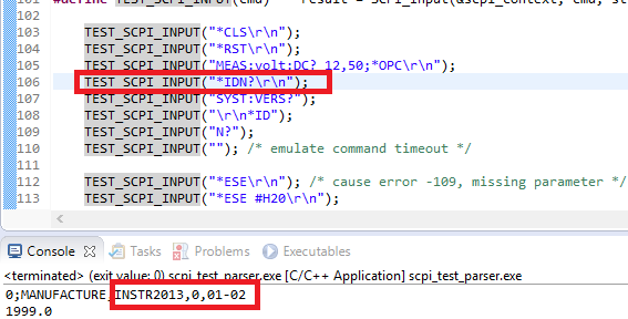
Here's a snippet of the test-parser example.


    TEST_SCPI_INPUT("*IDN?\r\n");
    TEST_SCPI_INPUT("SYST:VERS?");
    TEST_SCPI_INPUT("\r\n*ID");
    TEST_SCPI_INPUT("N?");
    TEST_SCPI_INPUT(""); /* emulate command timeout */


    TEST_SCPI_INPUT("*ESE\r\n"); /* cause error -109, missing parameter */
    TEST_SCPI_INPUT("*ESE #H20\r\n");


The TEST_SCPI_INPUT() macro is a wrapper around the lib's parser function


#define TEST_SCPI_INPUT(cmd)    result = SCPI_Input(&scpi_context, cmd, strlen(cmd))


In the examples, the "device under test" is - typical for unit tests - a mock implementation in software.

For the *IDN? command, it should return a concatenation of the following strings:


#define SCPI_IDN1 "MANUFACTURE"
#define SCPI_IDN2 "INSTR2013"
#define SCPI_IDN3 NULL
#define SCPI_IDN4 "01-02"


In my firmware, I'll have to provide the relevant values for my instrument.


The parser expects a callback function for each of the commands you support. In the mock implementation, Jan pretends that the instrument is a digital multimeter.


    {.pattern = "MEASure:VOLTage:DC?", .callback = DMM_MeasureVoltageDcQ,},
    {.pattern = "CONFigure:VOLTage:DC", .callback = DMM_ConfigureVoltageDc,},
    {.pattern = "MEASure:VOLTage:DC:RATio?", .callback = SCPI_StubQ,},
    {.pattern = "MEASure:VOLTage:AC?", .callback = DMM_MeasureVoltageAcQ,},
    {.pattern = "MEASure:CURRent:DC?", .callback = SCPI_StubQ,},
    {.pattern = "MEASure:CURRent:AC?", .callback = SCPI_StubQ,},
    {.pattern = "MEASure:RESistance?", .callback = SCPI_StubQ,},
    {.pattern = "MEASure:FRESistance?", .callback = SCPI_StubQ,},
    {.pattern = "MEASure:FREQuency?", .callback = SCPI_StubQ,},
    {.pattern = "MEASure:PERiod?", .callback = SCPI_StubQ,},


You can see handlers for MEASure requests and for CONFigure requests.

Here's the mock implementation that handles measuring DC voltage:


static scpi_result_t DMM_MeasureVoltageDcQ(scpi_t * context) {
    scpi_number_t param1, param2;
    char bf[15];
    fprintf(stderr, "meas:volt:dc\r\n"); /* debug command name */

    /* read first parameter if present */
    if (!SCPI_ParamNumber(context, scpi_special_numbers_def, ¶m1, FALSE)) {
        /* do something, if parameter not present */
    }

    /* read second parameter if present */
    if (!SCPI_ParamNumber(context, scpi_special_numbers_def, ¶m2, FALSE)) {
        /* do something, if parameter not present */
    }

    SCPI_NumberToStr(context, scpi_special_numbers_def, ¶m1, bf, 15);
    fprintf(stderr, "\tP1=%s\r\n", bf);

    SCPI_NumberToStr(context, scpi_special_numbers_def, ¶m2, bf, 15);
    fprintf(stderr, "\tP2=%s\r\n", bf);

    SCPI_ResultDouble(context, 0);

    return SCPI_RES_OK;
}


This is the output of my first debug session:


image


Most likely this library will be a fit for my purpose. At least functional.

I'll have to check if it doesn't use malloc(), UNION or other constructs that aren't allowed by MISRA. The first checks look promising.


Here's the full set of commands exercised by the test program:


    TEST_SCPI_INPUT("*CLS\r\n");
    TEST_SCPI_INPUT("*RST\r\n");
    TEST_SCPI_INPUT("MEAS:volt:DC? 12,50;*OPC\r\n");
    TEST_SCPI_INPUT("*IDN?\r\n");
    TEST_SCPI_INPUT("SYST:VERS?");
    TEST_SCPI_INPUT("\r\n*ID");
    TEST_SCPI_INPUT("N?");
    TEST_SCPI_INPUT(""); /* emulate command timeout */

    TEST_SCPI_INPUT("*ESE\r\n"); /* cause error -109, missing parameter */
    TEST_SCPI_INPUT("*ESE #H20\r\n");

    TEST_SCPI_INPUT("*SRE #HFF\r\n");

    TEST_SCPI_INPUT("IDN?\r\n"); /* cause error -113, undefined header */

    TEST_SCPI_INPUT("SYST:ERR?\r\n");
    TEST_SCPI_INPUT("SYST:ERR?\r\n");
    TEST_SCPI_INPUT("*STB?\r\n");
    TEST_SCPI_INPUT("*ESR?\r\n");
    TEST_SCPI_INPUT("*STB?\r\n");

    TEST_SCPI_INPUT("meas:volt:dc? 0.01 V, Default\r\n");
    TEST_SCPI_INPUT("meas:volt:dc?\r\n");
    TEST_SCPI_INPUT("meas:volt:dc? def, 0.00001\r\n");
    TEST_SCPI_INPUT("meas:volt:dc? 0.00001\r\n");

    TEST_SCPI_INPUT("test:text 'a'\r\n");
    TEST_SCPI_INPUT("test:text 'a a'\r\n");
    TEST_SCPI_INPUT("test:text 'aa a'\r\n");
    TEST_SCPI_INPUT("test:text 'aaa aaaa'\r\n");
    TEST_SCPI_INPUT("TEST:CHANnellist (@9!2:3!4,5!6)\r\n");


And here's the output (errors are expected - the program exercises fault handling too):


**Reset
meas:volt:dc
        P1=12
        P2=50
0;MANUFACTURE,INSTR2013,0,01-02
1999.0
MANUFACTURE,INSTR2013,0,01-02
**ERROR: -109, "Missing parameter"
**SRQ: 0x64 (100)
**ERROR: -113, "Undefined header"
-109,"Missing parameter"
**SRQ: 0x60 (96)
**ERROR: 0, "No error"
-113,"Undefined header;IDN?"
96
33
0
meas:volt:dc
        P1=0.01 V
        P2=DEFault
0
meas:volt:dc
        P1=1.112254449840
        P2=1.955364798282
0
meas:volt:dc
        P1=DEFault
        P2=1e-005
0
meas:volt:dc
        P1=1e-005
        P2=1.955364798282
0
TEXT: ***a***
TEXT: ***a a***
TEXT: ***aa a***
TEXT: ***aaa aaaa***
**SRQ: 0x44 (68)
**ERROR: -200, "Execution error"


Next Steps

I'll implement a serial interface on my test device with USB. And then I'll develop a single callback that supports *IDN?.

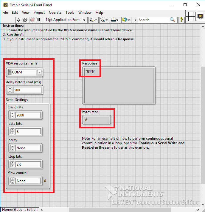
If I have that working, I can try to set up a conversation with LabVIEW.

(note to self: there's a test program in D:\Program Files (x86)\National Instruments\LabVIEW 2014\examples\Instrument IO\Serial\Simple Serial.vi)


Related Blog

Create a Programmable Instrument with SCPI - Part 1: Parser Library
Create a Programmable Instrument with SCPI - Part 2: Serial over USB
Create a Programmable Instrument with SCPI - Part 3: First Conversation *IDN?
Create a Programmable Instrument with SCPI - Part 4: Error Handling by Default
Create a Programmable Instrument with SCPI - Part 5: First Hardware Commands
Create a Programmable Instrument with SCPI - Part 6: LabVIEW Integration
Create a Programmable Instrument with SCPI - Part 7: Talk to Hardware Registers
  • Sign in to reply

Top Comments

  • DAB
    DAB over 8 years ago +1
    Nice post Jan. I had always been interested in using something like labview, but just never got around to it. The systems designs I had been doing were at a scale much larger than anything like labview…
  • Jan Cumps
    Jan Cumps over 8 years ago +1
    This isn't spectacular yet, but I have the first command working: Turn on or off PWM channel 1: PWM1:STATe ON PWM1:STATe OFF
  • Jan Cumps
    Jan Cumps over 8 years ago

    I've finished what I wanted to have. Full control of PWM signals with LabVIEW.


    The design can independently control 7 double PWM modules.

    Each module can have in-sync or complementary signals. The duty cycle of both signals can be controlled independently.

    I can set a deadband on either of the two signals - with different times.

    In LabVIEW, you can select one of the seven PMW modules, set the parameters and configure the device.


    Here's a capture:

    image


    The signals on the scope are the two outputs of PWM module 1.

    Both are at 50% duty cycle.

    There's an asymmetric deadband applied. It's longer for the rising edge of the blue signal. (The purple trace shows the deadband).

    • Cancel
    • Vote Up 0 Vote Down
    • Sign in to reply
    • More
    • Cancel
  • Jan Cumps
    Jan Cumps over 8 years ago

    added Create a Programmable Instrument with SCPI - Part 5: First Hardware Commands

    It's getting real now.

    • Cancel
    • Vote Up 0 Vote Down
    • Sign in to reply
    • More
    • Cancel
  • Jan Cumps
    Jan Cumps over 8 years ago

    This isn't spectacular yet, but I have the first command working:

    Turn on or off PWM channel 1:


    PWM1:STATe ON
    PWM1:STATe OFF


    image

    • Cancel
    • Vote Up +1 Vote Down
    • Sign in to reply
    • More
    • Cancel
  • Jan Cumps
    Jan Cumps over 8 years ago

    I've posted Create a Programmable Instrument with SCPI - Part 4: Error Handling by Default

    It shows how the open source SCPI library supports extendable error handling by default.

    • Cancel
    • Vote Up 0 Vote Down
    • Sign in to reply
    • More
    • Cancel
  • Jan Cumps
    Jan Cumps over 8 years ago

    I've posted part 3: Create a Programmable Instrument with SCPI - Part 3: First Conversation *IDN?


    With source code. This concludes the pure software and infrastructure part. I can start implementing real functions that do something electronically (PWM generation)

    • Cancel
    • Vote Up 0 Vote Down
    • Sign in to reply
    • More
    • Cancel
>
element14 Community

element14 is the first online community specifically for engineers. Connect with your peers and get expert answers to your questions.

  • Members
  • Learn
  • Technologies
  • Challenges & Projects
  • Products
  • Store
  • About Us
  • Feedback & Support
  • FAQs
  • Terms of Use
  • Privacy Policy
  • Legal and Copyright Notices
  • Sitemap
  • Cookies

An Avnet Company © 2025 Premier Farnell Limited. All Rights Reserved.

Premier Farnell Ltd, registered in England and Wales (no 00876412), registered office: Farnell House, Forge Lane, Leeds LS12 2NE.

ICP 备案号 10220084.

Follow element14

  • X
  • Facebook
  • linkedin
  • YouTube