


| For a hardware evaluation project I'm working on, I want to create a device that can be controlled via LabView. LabView can talk to instruments using serial out of the box, and it knows how to talk Standard Commands for Programmable Instruments (SCPI).
In this blog I'm writing the serial communication firmware for a Hercules safety microcontroller. |

SCPI Physical Communications Link is Undefined
SCPI does not care how you connect your two systems. That's what wikipedia says about SCPI - and it's true. You'll find instruments that can talk SCPI over TCP/IP, a GPIB interface, a serial port or via USB.
The heart of my test device is a Hercules RM46 LaunchPad. It has a USB connector that's bridged with one of the Hercules' serial communication modules.
On the PC, this USB is available as a COM port (UART).
Good enough for LabVIEW - it supports serial communication out of box.
Design Decisions for Serial Comms
Listening for LabVIEW commands isn't the only thing the test instrument will have to do. The SCPI interface is only one of its functionalities.
That means that we can't just sit there and wait for data to arrive on the serial comms interface. We'll have to use another strategy.
I'm using a real-time operating system (freeRTOS) as the basis for the firmware. That will make my work to look after multiple functionalities simpler.
I'll have a task that picks up any data sent over the USB and sends the info to the SCPI parser. But that task is not going to read from the USB.
To handle the part of fetching data and bringing it into the application scope, I'm setting up a Read interrupt.
The Hercules driver for SCI automatically runs in background mode when you do that (i.e.: the sciRead() function of that API returns immediately without reading the data - it just prepares the receive buffer).
Once the read interrupt fires, the data is ready.
Because the length of the SCPI commands are variable, I'm reading one character at a time and start processing the info when I receive a terminator character.
Configure the RTOS and the Serial Communication Driver
You configure Hercules microcontrollers with HALCogen. The tool will do four tasks for us.
- create source code for the freeRTOS Hercules port
- generate initialisation code for the peripherals - the serial communications module in this case
- configure clock, memory, interrupts
- generate source code for the device APIs - again for the serial comms module in this design.
HALCoGen is a round-trip configurator. You can safely switch between the tool and your source - both directions.
The first task is to opt for an RTOS project.
You do that when you create your project.
Select the correct controller, and opt for the FREERTOS entry.

You can set RTOS specific settings in a dedicated configuration pane.

That's it for the RTOS.
Later, when we ask HALCoGen to generate our project code, it will create the Hercules port sources and will put these configuration settings in the relevant freeRTOS config files.
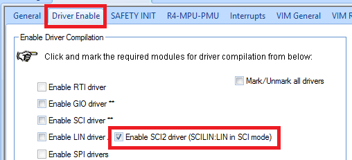
Next, we configure the serial communications device.
When you enable the driver, HALCoGen will create driver API source code.
Then you set the parameters. These will end up in the API's initialisation function.
I flag that I want to use the Read interrupt.

The baud rate is set to 9600, with 8,2,N (LabVIEW will have to use the same settings when talking to our instrument)


The last thing we have to do is enable the interrupt handler for the serial comms module.
Because we've configured High Level interrupt on the module page, we'll have to enable the corresponding high level interrupt in the vector.

HALCoGen can now generate our project sources. Over to the IDE.
Firmware
Because we use an RTOS, our main() is almost empty.
The first part calls the serial comms API init function to apply the settings we've done in HALCoGen.
Then we enable the interrupts.
The Read interrupt will fire from the moment we get data on the serial port.
The second part of main() registers our RTOS tasks and starts the engine.
void main(void)
{
/* USER CODE BEGIN (3) */
    sciInit();
    _enable_IRQ();

    // Register the command interpreter
    vStartUARTCommandInterpreterTask();

    // start RTOS
    vTaskStartScheduler();
    while(1);
/* USER CODE END */
}
We don't have to do anything in the serial communications interrupt handler (for now at least. We add functionality in the next blog post).
Just by defining that we want to use a read trigger, the API knows how to behave.
If you disable the read trigger, the serial comms API will run in blocking mode. if you call sciRead(size), the function will wait until you receive size bytes, and then return. The SCI buffer will contain the bytes read.
If you enable the read trigger, the API runs in non-blocking mode. If you call sciRead(size), the function prepares the buffer and trigger, and immediately returns. Your program can proceed with other things. When you receive size bytes, the trigger fires (and you can act on that if you want) and in parallel the data is available in the SCI buffer. |
In my firmware, I have an RTOS job that will pick up any character received, and that re-builds a SCPI command string from them.
Once the string is complete (when we receive a 0x0A character), we send it to the SCPI parser API, and return the result to LabVIEW.
... or, that's what will happen in the future. At this moment I just echo the string back, as a proof of concept.
void prvUARTCommandConsoleTask(void *pvParameters) {

    ( void ) pvParameters;
    _uRxChar = 0U;
    uint32_t i = 0L;

    sciReceive(scilinREG, 1, (uint8 *)&_uRxChar);

    for( ;; )
    {
        /* Only interested in reading one character at a time. */
        if (_uRxChar) {
            _uCommandBuffer[i] = _uRxChar;
            i++; // todo this must be controlled, reset the buffer after a command is finished or error when overrunning
            if (_uRxChar == 0x0A) {
                // we have a command. Send it to the parser queue
                // test implementation: echo
                sciSend(scilinREG, i, _uCommandBuffer); // todo remove this.

                i = 0U;
            }
            _uRxChar = 0U;
            sciReceive(scilinREG, 1, (uint8 *)&_uRxChar);
        }
    }
}
Test in LabVIEW
There's an example (Simple Serial) that sends the *IDN? command to a serial device, and shows the reply it receives from that device.
That's an excellent test bed candidate.
I need to set the serial parameters correctly. My Hercules LaunchPad USB is registered as COM4.

In HALCoGen, I had set up the serial parameters as 9600, 8, 2, N.
When I run the Simple Serial example, the SCPI command *IDN? is sent to COM4, and half a second later LabVIEW tries to read the reply.
Because my test firmware just sends the command back that it received, the program should show *IDN? in the result pane.
It should also show a data count of 6 (5 characters + the closing character 0x0A are all sent back).

Top Comments