element14 Community
element14 Community
    Register Log In
  • Site
  • Search
  • Log In Register
  • About Us
  • Community Hub
    Community Hub
    • What's New on element14
    • Feedback and Support
    • Benefits of Membership
    • Personal Blogs
    • Members Area
    • Achievement Levels
  • Learn
    Learn
    • Ask an Expert
    • eBooks
    • element14 presents
    • Learning Center
    • Tech Spotlight
    • STEM Academy
    • Webinars, Training and Events
    • Learning Groups
  • Technologies
    Technologies
    • 3D Printing
    • FPGA
    • Industrial Automation
    • Internet of Things
    • Power & Energy
    • Sensors
    • Technology Groups
  • Challenges & Projects
    Challenges & Projects
    • Design Challenges
    • element14 presents Projects
    • Project14
    • Arduino Projects
    • Raspberry Pi Projects
    • Project Groups
  • Products
    Products
    • Arduino
    • Avnet Boards Community
    • Dev Tools
    • Manufacturers
    • Multicomp Pro
    • Product Groups
    • Raspberry Pi
    • RoadTests & Reviews
  • Store
    Store
    • Visit Your Store
    • Choose another store...
      • Europe
      •  Austria (German)
      •  Belgium (Dutch, French)
      •  Bulgaria (Bulgarian)
      •  Czech Republic (Czech)
      •  Denmark (Danish)
      •  Estonia (Estonian)
      •  Finland (Finnish)
      •  France (French)
      •  Germany (German)
      •  Hungary (Hungarian)
      •  Ireland
      •  Israel
      •  Italy (Italian)
      •  Latvia (Latvian)
      •  
      •  Lithuania (Lithuanian)
      •  Netherlands (Dutch)
      •  Norway (Norwegian)
      •  Poland (Polish)
      •  Portugal (Portuguese)
      •  Romania (Romanian)
      •  Russia (Russian)
      •  Slovakia (Slovak)
      •  Slovenia (Slovenian)
      •  Spain (Spanish)
      •  Sweden (Swedish)
      •  Switzerland(German, French)
      •  Turkey (Turkish)
      •  United Kingdom
      • Asia Pacific
      •  Australia
      •  China
      •  Hong Kong
      •  India
      •  Korea (Korean)
      •  Malaysia
      •  New Zealand
      •  Philippines
      •  Singapore
      •  Taiwan
      •  Thailand (Thai)
      • Americas
      •  Brazil (Portuguese)
      •  Canada
      •  Mexico (Spanish)
      •  United States
      Can't find the country/region you're looking for? Visit our export site or find a local distributor.
  • Translate
  • Profile
  • Settings
Personal Blogs
  • Community Hub
  • More
Personal Blogs
Legacy Personal Blogs Create a Programmable Instrument with SCPI - Part 7: Talk to Hardware Registers
  • Blog
  • Documents
  • Mentions
  • Sub-Groups
  • Tags
  • More
  • Cancel
  • New
  • Share
  • More
  • Cancel
Group Actions
  • Group RSS
  • More
  • Cancel
Engagement
  • Author Author: Jan Cumps
  • Date Created: 30 Sep 2016 2:02 PM Date Created
  • Views 3306 views
  • Likes 6 likes
  • Comments 10 comments
  • smart_instrument
  • pwm
  • measurement
  • labview
  • scpi
  • automation
  • lab
  • instrument
Related
Recommended

Create a Programmable Instrument with SCPI - Part 7: Talk to Hardware Registers

Jan Cumps
Jan Cumps
30 Sep 2016
For a hardware evaluation project I'm working on, I want to create a device that can be controlled via LabVIEW.
LabVIEW can talk to instruments using serial out of the box, and it knows how to talk Standard Commands for Programmable Instruments (SCPI).


image


In this blog I adapt the LabVIEW Virtual Instrument and the firmware to give direct access to the Hercules PWM Time base control registers.

You'll be able to independently set all 7 PWM modules that are available on the controller.


The FirmWare Support for Direct Register Access

I provided a SCPI command that can receive a numeric value from LabVIEW and write that to the correct PWM module.

Here's the pattern:

    {.pattern = "PWM#:TBCTL", .callback = SCPI_HerculesPwmTBCTL,},


The implementation is very simple. Just like in the previous blog, we'll retrieve the PWM module, and the register value, from the SCPI command we get from LabVIEW.

LabView will send something like this:

PWM2:TBCTL #H200


We'll have to derive from this string that the PWM register set we have to address is that of PWM module 2.

And we'll have to write 0x0200 into its TBCTL register.


I have refactored my code since the first blog, to separate the Hercules PWM details from the SCPI parser. And I've factored out some functionality that can be reused accross many functions.

The code to get the right PWM module has gotten its own function:


static scpi_result_t PwmGetModule(scpi_t *context, uint32_t *uModule) {
  int32_t numbers[1];

  // retrieve the PWM channel. Can be 1 - 7
  SCPI_CommandNumbers(context, numbers, 1, 1);
  if (! ((numbers[0] > 0) && (numbers[0] < 8) )) {
  // todo push error on stack if the PWM CHANNEL not between 1 and 7
  return SCPI_RES_ERR;
  } else {
  *uModule = numbers[0];
  return SCPI_RES_OK;
  }
}


And here's the code that parses ut the register value and sends all to the Hercules PWM side:

/**
 * Set PWM register TBCTL
 *
 * Return SCPI_RES_OK
 *
 */
static scpi_result_t SCPI_HerculesPwmTBCTL(scpi_t * context) {

    int32_t param1;
    uint32_t uModule;
    if (PwmGetModule(context, &uModule) == SCPI_RES_ERR) {
        return SCPI_RES_ERR;
    }

     /* read first parameter if present */
     if (!SCPI_ParamInt32(context, &param1, TRUE)) {
         return SCPI_RES_ERR;
     }
     pwmTBCTL(uModule, param1);

    return SCPI_RES_OK;
}


In that PWM part, I simply write the value to the relevant register of the correct module:

// array of the 7 PWM registers of the RM46
etpwmBASE_t *pwmRegs[7] ={etpwmREG1, etpwmREG2, etpwmREG3, etpwmREG4, etpwmREG5, etpwmREG6, etpwmREG7} ;

void pwmTBCTL(uint32_t uModule, uint16_t uValue) {
  pwmRegs[uModule-1] -> TBCTL = uValue;
}


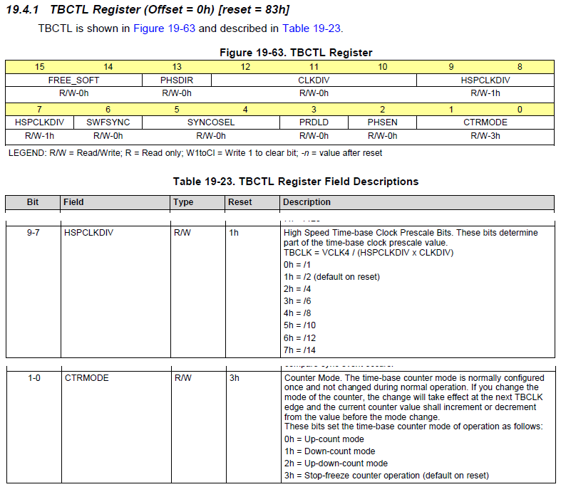
TBCTL is a 16 bit register that drives the following PWM behaviour (and more, that I don't discuss here):

Bit 9 - 7 are the high speed clock divider bits. A few examples

0b111: /14

0b001: /2

0b000: /1


Bit 1 - 0 indicate the counter mode. We'll use these two in our example:

0b00: normal up count

0b11: freeze counter


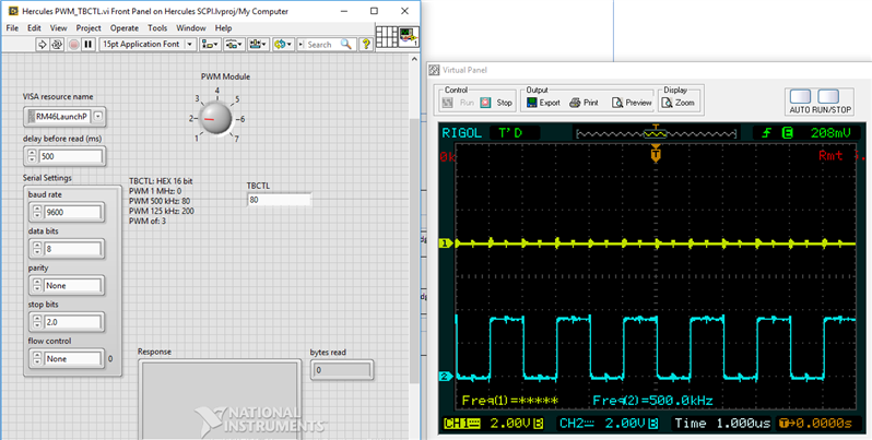
That's why you'll see the following useful Hex codes on the LabVIEW display below:

PWM 1 MHz: 0

PWM 500 kHz: 80

PWM 125 kHz: 200

PWM of: 3


This register isn't the one where you will later define the exact frequencies. I'll provide additional SCPI functionality to talk to those.

But for the things we want to show here - that we can select to what module we talk, and can push data to a register - TBCTL  will do just fine.


The LabVIEW Design

This version of the LabVIEW panel has two user editable controls.

There's a dial that allows you to select PWM module 1 to 7.

image


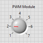
When you run the LabVIEW process, it will talk to that PWM module of your Hercules LaunchPad.


The second control is an edit box where you can type the hexadecimal value of what you want to write to that PWM module's TBCTL  register.

image

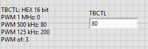
For convenience, I've added a table with some useful values next to it.

Use this edit box together with your controller's technical reference manual.

The LabVIEW program here is a great tool for you to better learn your controller's PWM module.

You can type in any value you like (better base it on the instructions in the TRM image ), and beam them directly into the register.

You can attach a scope and see the results.


Here's the very simple LabVIEW block diagram.

image

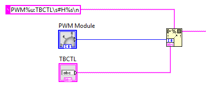
The string constant holds the following value:

PWM%u:TBCTL\s#H%s\n


That is sent into a Format Into String block, together with the values of the dial and the edit control.

At the output of the block, you'll get:

PWM2:TBCTL #H80\n


That is sent off to the Hercules LaunchPad over USB.


The results

Let's see how the outputs of PWM module 1 and 2 look lik when we send a few commands.


After sending 0x3 to both modules (both off):

image


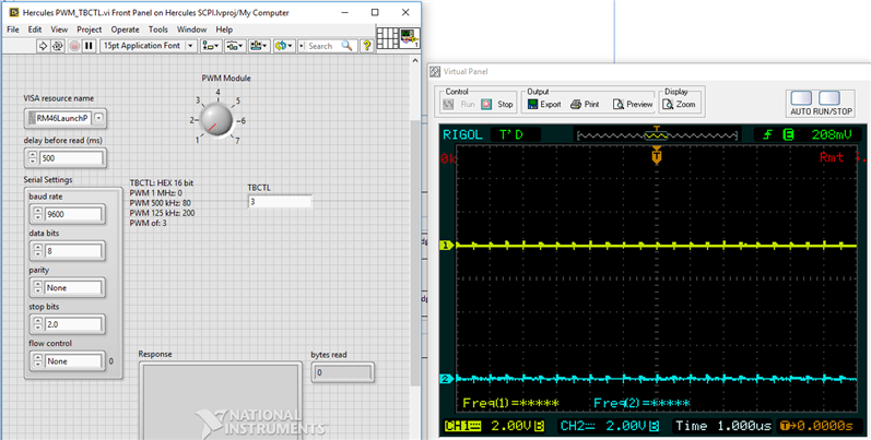
After sending 0x80 to PWM 2 (500kHz):

image


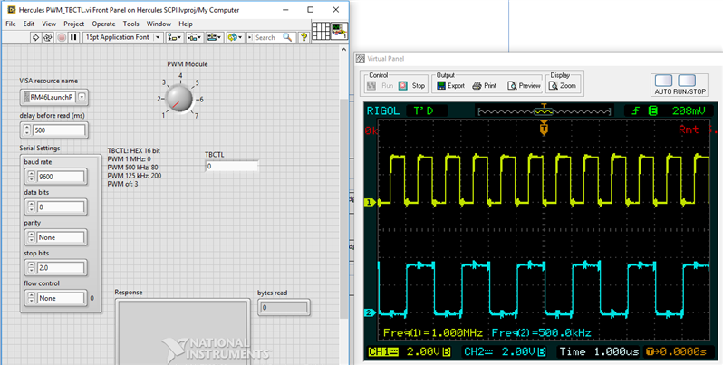
After sending 0x0 to PWM 1 (1MHz):


image


It's easier to understand why 0x03 switches off the PWM signal and why the other magical HEX values do what they do if you know the layout of the register we're addressing. Here are the relevant bits explained.

Source:  http://www.ti.com/lit/pdf/spnu514

image


The source for LabVIEW and the Hercules CCS project are attached to this blog.

You can try this yourself.


Related Blog

Create a Programmable Instrument with SCPI - Part 1: Parser Library
Create a Programmable Instrument with SCPI - Part 2: Serial over USB
Create a Programmable Instrument with SCPI - Part 3: First Conversation *IDN?
Create a Programmable Instrument with SCPI - Part 4: Error Handling by Default
Create a Programmable Instrument with SCPI - Part 5: First Hardware Commands
Create a Programmable Instrument with SCPI - Part 6: LabVIEW Integration
Create a Programmable Instrument with SCPI - Part 7: Talk to Hardware Registers
Attachments:
blog.zip
  • Sign in to reply

Top Comments

  • Jan Cumps
    Jan Cumps over 7 years ago in reply to fmilburn +3
    Frank, Processor power will not be an issue. You'll have to check if the MSP430 has enough memory left for your non-SCPI firmware though. I could not fit the library in an Arduino (that has 32 K RAM too…
  • jc2048
    jc2048 over 7 years ago in reply to fmilburn +3
    Something to watch if you try the SCPI parser is that it uses allocated dynamic memory when it runs. The amount depends on the command tree that you define. I found on the Arduino that just adding a couple…
  • DAB
    DAB over 8 years ago +2
    Great update Jan. Getting the control sequence right sets up project for lots of expansion. DAB
  • Jan Cumps
    Jan Cumps over 7 years ago in reply to jc2048

    That library for Arduino is a different one. I think that the one I’m using in this project doesn’t dynamically allocate as far as I’m aware.

    • Cancel
    • Vote Up +2 Vote Down
    • Sign in to reply
    • More
    • Cancel
  • fmilburn
    fmilburn over 7 years ago in reply to jc2048

    Hi Jon and thanks. That is useful info in your post and in the comments below it.

    • Cancel
    • Vote Up +2 Vote Down
    • Sign in to reply
    • More
    • Cancel
  • jc2048
    jc2048 over 7 years ago in reply to fmilburn

    Something to watch if you try the SCPI parser is that it uses allocated dynamic memory when it runs. The amount depends on the command tree that you define. I found on the Arduino that just adding a couple of SCPI commands exceeded the user ram that I had left, but then I didn't have much RAM to play with to start with because of the sine table I had in there. You'll do much better with 4k of SRAM, but it's still something to watch if you use a lot of the SRAM for your own variables. [On the Arduino it's a bit baffling because it's a run-time error and there isn't an easy way to see what's happening, but you'll be fine if you run it debug on CCS as you'll see it gobbling up the memory.]


    Arduino: R-2R: Setting the Signal Amplitude

    • Cancel
    • Vote Up +3 Vote Down
    • Sign in to reply
    • More
    • Cancel
  • fmilburn
    fmilburn over 7 years ago in reply to Jan Cumps

    Thanks for the advice and heads up Jan. My device should not need much memory and not having the Arduino overhead and the bootloader should help.  I will give it a try.

    • Cancel
    • Vote Up +2 Vote Down
    • Sign in to reply
    • More
    • Cancel
  • Jan Cumps
    Jan Cumps over 7 years ago in reply to fmilburn

    Frank,


    Processor power will not be an issue. You'll have to check if the MSP430 has enough memory left for your non-SCPI firmware though.

    I could not fit the library in an Arduino (that has 32 K RAM too - but 5 K of that taken by the bootloader) using its standard toolset.


    The best way to try is to build a proof of concept, compile it and check the memory map to see how much you have left for your device's logic.


    edit:

    For now I don't plan to connect to LabView - just a terminal.

    This works perfectly. The only thing you have to take into account that SCPI does not echo the text you type. With most terminal programs, you will not see on the screen what you are typing with standard settings..

    In PuTTY, these settings allow you to see your command string - and edit it before sending to your controller;


    image

    • Cancel
    • Vote Up +3 Vote Down
    • Sign in to reply
    • More
    • Cancel
>
element14 Community

element14 is the first online community specifically for engineers. Connect with your peers and get expert answers to your questions.

  • Members
  • Learn
  • Technologies
  • Challenges & Projects
  • Products
  • Store
  • About Us
  • Feedback & Support
  • FAQs
  • Terms of Use
  • Privacy Policy
  • Legal and Copyright Notices
  • Sitemap
  • Cookies

An Avnet Company © 2025 Premier Farnell Limited. All Rights Reserved.

Premier Farnell Ltd, registered in England and Wales (no 00876412), registered office: Farnell House, Forge Lane, Leeds LS12 2NE.

ICP 备案号 10220084.

Follow element14

  • X
  • Facebook
  • linkedin
  • YouTube