


CurSns2 – Current Sense Resistors.
24 Feb 2015
This section, CurSns2, will cover Current Sense Resistors (RSense) in different circuit configurations:
- Low-Side
- High-Side
- 2-Wire
- 4-Wire
A current sensor is used to convert current to an easily measured voltage that is proportional to current. There are a wide variety of sensors as discussed in the blog: https://electronicsknowhowblog.wordpress.com/2015/02/18/current-sensors/
and Current Sensor 1. Introduction.
Each type of sensor is useful in a certain range of currents and environment. Among these sensors, the Current Sense Resistor or current shunt is the most common. The Current Sense Resistor uses ohm’s law to generate a voltage as RSense x Measured Current. This simple method has some advantages and disadvantages:
Advantages of using RSense:
- Low Cost
- Good measurement accuracy is possible
- Measurement range from mA to hundreds of amps
- Capable of measuring AC and DC current
Disadvantages:
- There is an added resistance in the circuit path
- There is power loss in the resistor I2 x RSense
- The circuit has to be broken to make a temporary measurement
- There will be issues of grounding the voltage measurement device
When choosing a component to be used as RSense some criteria are:
- Low resistance and tight tolerance to achieve accuracy with low dissipation
- Current carrying capability must include transient fault conditions
- Low inductance to minimise EMF due to high frequency components
- Low temperature coefficient, low thermal EMF for wide range of temperature operation
The RSense resistor can be installed on the low voltage side of the load or on the high voltage side with different pros and cons.
Low-Side Current Sensing.
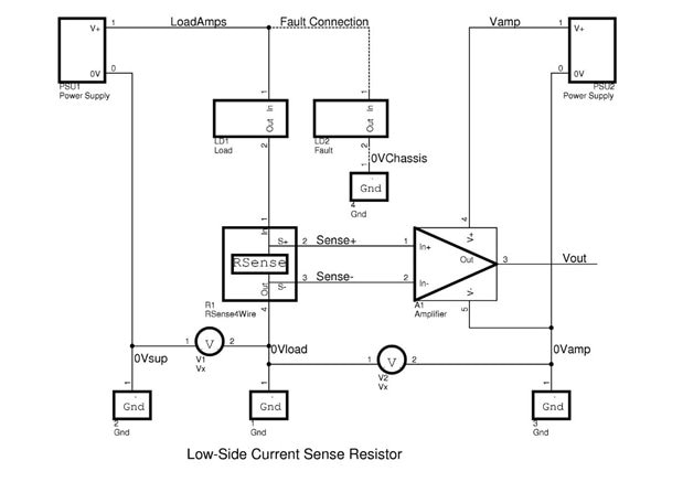
Figure 1. Low-Side Current Sensing
RSense is shown between the Load LD1 and ground; the output is usually low, for example, full scale may be 50mV, so an amplifier A1 is used to generate a scaled output Vout. There are pros and cons of using a low-side RSense connection.
Advantages:
- Simple and low cost
- Low common mode voltage as the amplifier is referenced to the same ground as RSense. Can use a relatively simple OpAmp amplifier circuit but it must work down to ground on the input side.
- No need to use isolated amplifiers or isolated power supply PSU2 as there is a common ground
Disadvantages:
- There may be voltages V1 and V2 between the grounding points in the circuit. These will be minimised in a tightly coupled measurement where the circuit is all local; on a PCB for example.
- If there is fault current through LD2, for example a short to chassis, then the fault current is not measured by RSense. Much depends on whether you want to control fault currents via a current limit that depends on the measurement of Vout. If you do not need to measure the fault current then, in this configuration, RSense does not need to be rated for high fault currents, which you may regard as an advantage!
High-Side Current Sensing.

Figure 2. High-Side Current Sensing
In this configuration, RSense is between the supply PSU3 and the load LD3. Again the voltage will be amplified by A2 to generate a scaled output Vout. And there are some more pros and cons.
Advantages:
- The Load is grounded directly
- Fault currents through LD4 will be detected by RSense
Disadvantages:
- Must be able to handle high common mode voltages if V4 is high
- The circuit is more complex if V4 is high
- And as a consequence the cost is higher.
Nevertheless, there are many applications where high-side current measurement is desirable and is indeed used. For example, high side measurement is used if the load must be grounded, floating, or short circuit measurement is needed, such as in motor current measurement, over-current protection, automotive power circuits and battery monitoring.
We will come back to the choice of RSense in some real applications and the design of the amplifier to accommodate the high common mode voltage.
The circuits in Figures 1 and 2 showed the RSense component with 4 terminals and 4-wire Kelvin connection; however it is possible to use a 2-wire connection.
2-wire Connection.

Figure 3. A 2-wire High-Side Connection.
This configuration shows the voltage being measured across the RSense resistor as well as part of the wire that connects it to the load. Obviously this introduces an error in the measurement as the voltage at V5 will be LoadAmps x (RSense + Wire1Resistance + Wire2Resistance). The result we want is LoadAmps x RSense so the error is LoadAmps x (Wire1Resistance + Wire2Resistance). If the length of Wire1 and Wire2 is many meters it is tempting to use a 2-wire connection to reduce the cost and weight of the cabling (weight is of concern in an aircraft). However the value of Wire1Resistance and Wire2Resistance may be high compared to RSense and this error must be a trade-off in the design if the error can be tolerated.
4-wire Connection (also called Kelvin Connection).

Figure 4. 4-wire high-side connection.
In this configuration, RSense has 4 terminals. The load current passes through RSense but 2 other terminals are provided for the measurement of voltage. These sense terminals are connected across the resistive element in such a way as to minimise the resistance of the power terminals. Some resistors are fitted with these sense terminals otherwise, for example on a PCB, the sense terminals are connected to the component pads. The sense terminals should be connected to a measurement that takes very little current compared to the load current being measured in order to minimise errors. 4-wire connection achieves better accuracy that 2-wire as the error due to Wire1Resistance and Wire2Resistance has been eliminated as the value of V6 is RSense x LoadAmps. However there is a price to pay as the wiring is more complex, more expensive and heavier as the signal wires S+ and S- have been added.
Current Sense Resistor in a DC kWh meter.

The Current Sense Resistor RSense in the DC Meter is connected in a Low-Side 4-wire configuration. Low-Side measurement was defined in the product requirement and 4-wire connection was used for accuracy. As the connections are all local on the PCB, voltage drops between the ground reference connections could be minimised and the local power supply was referenced on a star point made at the 0V connection of RSense. Note that the component has 5 connections, the fifth being the star point.
The Current Sense Resistor in this product is SH1, it is a PCB mounted current shunt - VISHAY DALE WSMS2908L5000JK RESISTOR, METER SHUNT, R0005, 5% Farnell Part number 1858301.
Terminal 1 is connected to the load return and terminal 4 to the supply 0V. Terminals 2 and 3 are connected to the differential amplifier via the connector J4. Terminal 5 was used as the star point for the local power supply derived from the DC input bus.
Current Sense Resistor – 200A shunt – in a Motor Test Stand.

The Current Sense Resistors RSense in the Motor Test Stand are connected in a High-Side 4-wire configuration. High-Side connection was chosen as 3-phase motor currents flow in a circuit that cannot be grounded, indeed RSense floats on a complex voltage waveform derived from the 3-phase motor control inverter. We will be coming back to this application as it is a good example of the use of isolation amplifiers to measure the output of floating RSense components.
The Current Sense Resistors are 200A shunts scaled to 50mV output from MURATA POWER SOLUTIONS 3020-01101-0 SHUNT, 50MV 200A, Farnell Part Number 1339341.
Terminal 1 is connected in the phase supply and terminal 4 to the motor phase. Terminals 2 and 3 are connected to a differential amplifier 5 via the screened twisted-pair cable. An overall grounding scheme was used with a local star point – grounding schemes and isolation will be discussed again later. We will also discuss the use of an RSense component vs a non-invasive current sensor that has inherent isolation.
This blog will be available at element14 community.
Here are a few useful references.
http://www.eetimes.com/document.asp?doc_id=1279404
http://www.allaboutcircuits.com/vol_1/chpt_8/9.html
Top Comments