


For my DC Motors Mobile Robot I am using an Arduino Nano (with no connectors soldered in) and a dual DC motor driver (DRV8833) which now fit nicely inside the 3D printed chassis. I now need to make all the connections between these two PCBs and the four micro DC motors. In the past I have soldered wires directly but this caused me endless problems when trouble shooting so I decided to solder DuPont connecting wires instead. I cut off one connector, soldered one wire to one PCB and the other wire to the other PCB. By careful soldering this worked fine and the two PCBs still fit into their 3D printed holder, with the added advantage that I an use the colour of the wires to ensure proper connections. Once all the wires had been soldered on the PCBs were then refitted to the mobile robot chassis, as illustrated in the photograph below.
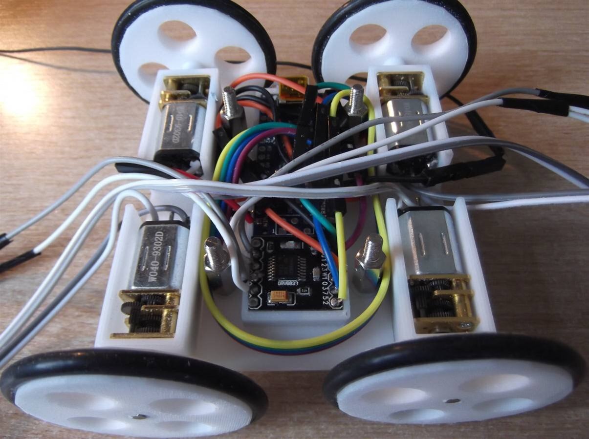
As can be seen, despite my previous optimism that all would be well, there are many more wires and DuPont connectors than I had realised and I cannot get them all to fit inside the chassis. I have also realised that I have not included any form of ON/OFF switch. Plus, I have not yet added the wires for controlling the micro servo motor and the LEDs/sensors in the top dome. Still, the PCBs are inside the chassis along with about half the existing wires and there is just enough wire to use the power connectors as the power on/off, as show in the video below.
I will have to have a think now and decide whether to shorten the wires so that everything will fit inside, or make the chassis base larger so that everything will fit inside.I am leaning more towards making the chassis base larger as I think that would be easier (and 3D printing/design is fun - soldering not so much) and allow me the opportunity to add some sort of on/off switch.
Dubbie
Top Comments