element14 Community
element14 Community
    Register Log In
  • Site
  • Search
  • Log In Register
  • Community Hub
    Community Hub
    • What's New on element14
    • Feedback and Support
    • Benefits of Membership
    • Personal Blogs
    • Members Area
    • Achievement Levels
  • Learn
    Learn
    • Ask an Expert
    • eBooks
    • element14 presents
    • Learning Center
    • Tech Spotlight
    • STEM Academy
    • Webinars, Training and Events
    • Learning Groups
  • Technologies
    Technologies
    • 3D Printing
    • FPGA
    • Industrial Automation
    • Internet of Things
    • Power & Energy
    • Sensors
    • Technology Groups
  • Challenges & Projects
    Challenges & Projects
    • Design Challenges
    • element14 presents Projects
    • Project14
    • Arduino Projects
    • Raspberry Pi Projects
    • Project Groups
  • Products
    Products
    • Arduino
    • Avnet & Tria Boards Community
    • Dev Tools
    • Manufacturers
    • Multicomp Pro
    • Product Groups
    • Raspberry Pi
    • RoadTests & Reviews
  • About Us
  • Store
    Store
    • Visit Your Store
    • Choose another store...
      • Europe
      •  Austria (German)
      •  Belgium (Dutch, French)
      •  Bulgaria (Bulgarian)
      •  Czech Republic (Czech)
      •  Denmark (Danish)
      •  Estonia (Estonian)
      •  Finland (Finnish)
      •  France (French)
      •  Germany (German)
      •  Hungary (Hungarian)
      •  Ireland
      •  Israel
      •  Italy (Italian)
      •  Latvia (Latvian)
      •  
      •  Lithuania (Lithuanian)
      •  Netherlands (Dutch)
      •  Norway (Norwegian)
      •  Poland (Polish)
      •  Portugal (Portuguese)
      •  Romania (Romanian)
      •  Russia (Russian)
      •  Slovakia (Slovak)
      •  Slovenia (Slovenian)
      •  Spain (Spanish)
      •  Sweden (Swedish)
      •  Switzerland(German, French)
      •  Turkey (Turkish)
      •  United Kingdom
      • Asia Pacific
      •  Australia
      •  China
      •  Hong Kong
      •  India
      •  Korea (Korean)
      •  Malaysia
      •  New Zealand
      •  Philippines
      •  Singapore
      •  Taiwan
      •  Thailand (Thai)
      • Americas
      •  Brazil (Portuguese)
      •  Canada
      •  Mexico (Spanish)
      •  United States
      Can't find the country/region you're looking for? Visit our export site or find a local distributor.
  • Translate
  • Profile
  • Settings
Personal Blogs
  • Community Hub
  • More
Personal Blogs
Legacy Personal Blogs Digital Electronics : Basic Logic Operations and Circuits
  • Blog
  • Documents
  • Mentions
  • Sub-Groups
  • Tags
  • More
  • Cancel
  • New
  • Share
  • More
  • Cancel
Group Actions
  • Group RSS
  • More
  • Cancel
Engagement
  • Author Author: matija.martinec
  • Date Created: 27 Dec 2014 11:49 AM Date Created
  • Views 6969 views
  • Likes 4 likes
  • Comments 3 comments
  • logic
  • digi
  • digital
  • nor
  • xnor
  • nand
  • circuit
  • operation
  • and
  • xor
  • electronics
  • basic
  • not
  • functions
  • or
Related
Recommended

Digital Electronics : Basic Logic Operations and Circuits

matija.martinec
matija.martinec
27 Dec 2014

Hello everyone, in this post I will go over basic logic operations and their circuits :


First of all we need to define some Boolean data types and notation. We need to go over this because without basic knowledge about boolean algebra we can't work with logic operations and circuits


There are only 2 types of data in boolean algebra : HIGH (logic state 1 ) & LOW (logic state 0 ) --> ! Common mistake people make is that when they see a complex logic function they say that there can be practically indefinite number of data or when they see it "Letters" (e.g. Y = ((A + B')' * (C + D')')' ) we will get to notation in just a bit), but that is not type of data, those are variables which contain that type of data


    • 1 is noted HIGH because it represents high voltage level
    • 0 is noted LOW because it represents low voltage level


This is the notation and algebraic expressions for logic functions (we will get over each one in depth) :

  • Y = A - Y is output and A is a variable

BASIC

  • Y = A' - ' is an inverter (e.g. A' is inverted of A so if A = 0 then A' = 1)
  • Y = A * B - logic operation AND (A AND B)
  • Y = A + B - logic operation OR (A OR B)
  • Y = (A * B)' - logic operation NAND (NOT AND - A AND B INVERTED)
  • Y = (A + B)' - logic operation NOR (NOT OR - A OR B INVERTED)


**I will not be covering XOR or X NOR, the reason is that I only need the upper ones for my future posts "hint, hint" **

  • Y = A * B' + A' * B - logic operation XOR (EXCLUSIVE OR)
  • Y = (A * B' + A' * B)' - logic operation XNOR (EXCLUSIVE NOT OR)


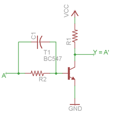
Logic operation/circuit NOT


Logic circuit NOT preforms logic operation of an INVERTER (inversion).Circuit can have only 1 input and 1 output. On the output Y we will have different logic state than on the input.


Algebraic expression  :

Y = A'


Symbol :

  • MIL/ANSI

image

  • IEC

image

Table of truth:

INPUTOUTPUT
ANOT A
01
10


Electrical schematic:

image


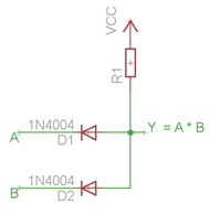
Logic operation/circuit AND


Logic circuit AND preforms logic operation AND. Circuit can have 2 or MORE inputs and only 1 output. At output Y we will have logic state 1 only then when all of our inputs are in logic state 1, and if any of the in puts is in logic state 0 we will have logic state 0 on the output Y.


Algebraic expression  :

Y = A * B


Symbol :

  • MIL/ANSI

AND ANSI.svg

  • IEC

AND IEC.svg

Table of truth:

INPUTOUTPUT
ABA AND B
000
010
100
111


Electrical schematic:

image

Logic operation/circuit OR


Logic circuit OR preforms logic operation OR. Circuit can have 2 or MORE inputs and only 1 output. At output Y we will have logic state 0 only when all of our inputs are in logic state 0, if any or all inputs are in logic state 1 output Y will be in logic state 1.


Algebraic expression  :

Y = A + B


Symbol :

  • MIL/ANSI

OR ANSI Labelled.svg

  • IEC

IEC OR.svg

Table of truth:

INPUTOUTPUT
ABA OR B
000
011
101
111


Electrical schematic:

image

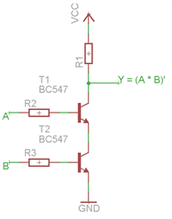
Logic operation/circuit NAND


Logic circuit NAND preforms logic operation NOT AND. Circuit can have 2 or MORE inputs and only 1 output. At output Y we will have logic state 0 only then when all of our inputs are in logic state 1, and if any of the in puts is in logic state 0 we will have logic state 1 on the output Y.


Algebraic expression  :

Y = (A * B)'


Symbol :

  • MIL/ANSI

NAND ANSI Labelled.svg

  • IEC

NAND IEC.svg

Table of truth:

INPUTOUTPUT
ABA NAND B
001
011
101
110


Electrical schematic (With transistors):

image

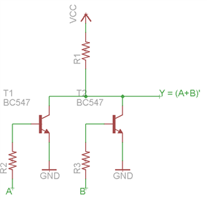
Logic operation/circuit NOR


Logic circuit NOR preforms logic operation NOT OR. Circuit can have 2 or MORE inputs and only 1 output. At output Y we will have logic state 1 only when all of our inputs are in logic state 0 and if any of the inputs is in logic state 1 we will have logic state 0 on the output Y.


Algebraic expression  :

Y =( A + B )'


Symbol :

  • MIL/ANSI

NOR ANSI Labelled.svg

  • IEC

NOR IEC.svg

Table of truth:

INPUTOUTPUT
ABA NAND B
001
010
100
110


Electrical schematic (With transistors):

image


I think this would be all that is needed for anyone to start with digital electronics, bare bones of digital electronics. In the next post related to digital electronics I will start to talk about complex logic functions, how to minimize them in a few ways and then  how to realize/make them with logic circuits.

I hope you enjoyed this quick post, if you did please like it and if you did not please tell me why so I can get better. Also if you detect any errors please let me know via PM so you leave space in the comment section for some questions.


Until next time,

Matija Martinec

  • Sign in to reply

Top Comments

  • jw0752
    jw0752 over 10 years ago +1
    Hi Matija, Very nice presentation. I learned some new things and I liked the way you provided circuit schematics for the different logics that you covered. Your friends are missing a wonderful opportunity…
  • DAB
    DAB over 10 years ago +1
    Good tutorial. It takes me back a lot of years. We used to implement basic logic circuits using tubes and we were very happy when we got to transistors and integrated circuits. DAB
  • DAB
    DAB over 10 years ago

    Good tutorial.


    It takes me back a lot of years.

    We used to implement basic logic circuits using tubes and we were very happy when we got to transistors and integrated circuits.


    DAB

    • Cancel
    • Vote Up +1 Vote Down
    • Sign in to reply
    • More
    • Cancel
  • matija.martinec
    matija.martinec over 10 years ago in reply to jw0752

    John, thank you again image, this is merely the basics, in school we are learning much more but I will cover more in other topics when it is going to be needed.

    Matija

    • Cancel
    • Vote Up 0 Vote Down
    • Sign in to reply
    • More
    • Cancel
  • jw0752
    jw0752 over 10 years ago

    Hi Matija,  Very nice presentation. I learned some new things and I liked the way you provided circuit schematics for the different logics that you covered. Your friends are missing a wonderful opportunity to learn from you. Keep up the good work. Look at the number of people that read your posts and you will see that there are many interested people.

    John

    • Cancel
    • Vote Up +1 Vote Down
    • Sign in to reply
    • More
    • Cancel
element14 Community

element14 is the first online community specifically for engineers. Connect with your peers and get expert answers to your questions.

  • Members
  • Learn
  • Technologies
  • Challenges & Projects
  • Products
  • Store
  • About Us
  • Feedback & Support
  • FAQs
  • Terms of Use
  • Privacy Policy
  • Legal and Copyright Notices
  • Sitemap
  • Cookies

An Avnet Company © 2025 Premier Farnell Limited. All Rights Reserved.

Premier Farnell Ltd, registered in England and Wales (no 00876412), registered office: Farnell House, Forge Lane, Leeds LS12 2NE.

ICP 备案号 10220084.

Follow element14

  • X
  • Facebook
  • linkedin
  • YouTube