


Having an organized work area is a must when working with electronics. Having an extra pair of hands and plenty of light is also essential. This is why after looking at DIY workstations built by many other electronics enthusiasts I decided to build my own.
This started out as a rainy day project while I work on my shop. So as it get too cold, too dark, or too rainy, I will share my progress in this series. I learned along the way that you can make pretty good dado cuts with a Radial arm saw. So I modified my design to use half lap joints.
The full project will feature:
- ESD Protection
- AC Power outlets
- Plenty of LED lighting
- A spotlight aimed with Loc-Line
- Plenty of extra hands made with Loc-Line
- A fume extractor
- A powered USB outlet and a 12V DC line
- A mount for an extra pair of hands/magnifier combo.
- A top shelf for storage bins.
Here is a picture of all the pieces cut and roughed together (NOTE: The cut outs for the outlets and fume extractor are not yet made).
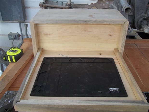
This is a rough cut, but the base will be ready to glue and clamp after some sanding.
The base is 14" X 16". I butt joined two 1X8's to make it. Of course, I surrounded the base with a lip because I am notorious for dropping small screws and hate crawling around the floor looking for them. The black pad is an ESD safe repair mat. I chose this mat because it is not only the right size, but it also has a temperature coefficient of 300C for hot air and can take a 230C direct hit. The built in trays should also help me save some headache caused by screws and such. However, this mat doesn't have a lug, so I will set it on top of a piece of grounded flashing to make sure it doesn't build up electrons. I will also put a piece of 12X12" tile under the mat to help diffuse heat.(You can find out more about this ESD mat here).
The first step for this project is making the base. This is what I did:
- Butt joined two 1X8" together with Gorilla Wood Glue.
- Cut the joined 1X8's square at 14"
- Ripped another scrap piece of 1X8 into 1.5" sticks.
- Cut the 1X8's to length for the front and the sides, allowing for the overhang.
- Made the dado cuts for the half lap joints.
- Dry fit the pieces together and made adjustments as necessary.
- Sanded the lapped out portions.
- Clamepd and glued.
Some notes:
- Make your cuts too long. It is easier to cut a blade's width more off. Most of us don't posses a board stretcher
 .
. - Use a C clamp to hold your sides when lapping out the bottom. Also, use another stick to move the wood slightly while cutting. Be careful so as not to lose fingers.
- Dry fit the pieces as you go. Cut too short or too long as the case may be. Then as you dry fit, shave off a little bit and dry fit it again. Repeat this until you have a good fit.

Here is an exploded view of the base made in OpenScad.
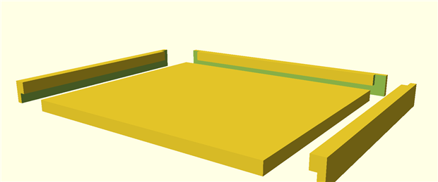
Side View
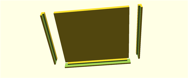
Bottom View
Code:
//Base
cube([14.25,16,0.75]);
//Right Side
translate([-0.5, -3, 0])
difference(){
cube([14.5,0.75, 1.5]);
translate([-0.005,0.37505,-0.05]) cube([14.51,0.3751, 0.75]); // Bottom lap
translate([-0.005,0.375,0.005]) cube([0.751, 0.3751, 1.751]); // Corner lap
}
//Left Side
translate([-0.5, 18, 0])
difference(){
cube([14.5,0.75, 1.5]);
translate([-0.005,-0.0005, -0.005]) cube([14.51,0.3751, 0.751]); // Bottom lap
translate([-0.005,-0.0005,0.005]) cube([0.751, 0.3751, 1.751]); // Corner lap
}
//Front
translate([-2,-0.50,0])
difference(){
cube([0.75,17, 1.5]);
translate([0.375,-0.005,-0.0005]) cube([0.3751,17.01, 0.751]); // Bottom lap
translate([0.37505,-0.005,-0.0005])cube([0.375,0.75,1.75]); // Right corner lap
translate([0.37505,16.25,-0.0005])cube([0.375,0.7505,1.75]); // Left corner lap
}
The next post shows the completed base and the steps necessary to get a good joint. After that we will add the mounts to the base. Then we will cut out the back for the fume extractor and outlets, add the sides and top. Until next time...