element14 Community
element14 Community
    Register Log In
  • Site
  • Search
  • Log In Register
  • Members
    Members
    • Benefits of Membership
    • Achievement Levels
    • Members Area
    • Personal Blogs
    • Feedback and Support
    • What's New on element14
  • Learn
    Learn
    • Learning Center
    • eBooks
    • STEM Academy
    • Webinars, Training and Events
    • Learning Groups
  • Technologies
    Technologies
    • 3D Printing
    • Experts & Guidance
    • FPGA
    • Industrial Automation
    • Internet of Things
    • Power & Energy
    • Sensors
    • Technology Groups
  • Challenges & Projects
    Challenges & Projects
    • Design Challenges
    • element14 presents
    • Project14
    • Arduino Projects
    • Raspberry Pi Projects
    • Project Groups
  • Products
    Products
    • Arduino
    • Dev Tools
    • Manufacturers
    • Raspberry Pi
    • RoadTests & Reviews
    • Avnet Boards Community
    • Product Groups
  • Store
    Store
    • Visit Your Store
    • 'Choose another store...'
      • Europe
      •  Austria (German)
      •  Belgium (Dutch, French)
      •  Bulgaria (Bulgarian)
      •  Czech Republic (Czech)
      •  Denmark (Danish)
      •  Estonia (Estonian)
      •  Finland (Finnish)
      •  France (French)
      •  Germany (German)
      •  Hungary (Hungarian)
      •  Ireland
      •  Israel
      •  Italy (Italian)
      •  Latvia (Latvian)
      •  
      •  Lithuania (Lithuanian)
      •  Netherlands (Dutch)
      •  Norway (Norwegian)
      •  Poland (Polish)
      •  Portugal (Portuguese)
      •  Romania (Romanian)
      •  Russia (Russian)
      •  Slovakia (Slovak)
      •  Slovenia (Slovenian)
      •  Spain (Spanish)
      •  Sweden (Swedish)
      •  Switzerland(German, French)
      •  Turkey (Turkish)
      •  United Kingdom
      • Asia Pacific
      •  Australia
      •  China
      •  Hong Kong
      •  India
      •  Korea (Korean)
      •  Malaysia
      •  New Zealand
      •  Philippines
      •  Singapore
      •  Taiwan
      •  Thailand (Thai)
      • Americas
      •  Brazil (Portuguese)
      •  Canada
      •  Mexico (Spanish)
      •  United States
      Can't find the country/region you're looking for? Visit our export site or find a local distributor.
  • Translate
  • Profile
Personal Blogs
  • Members
  • More
Personal Blogs
Legacy Personal Blogs DIY Soldering Station Part 5
  • Blog
  • Documents
  • Mentions
  • Sub-Groups
  • Tags
  • More
  • Cancel
  • New
Blog Post Actions
  • Subscribe by email
  • More
  • Cancel
  • Share
  • Subscribe by email
  • More
  • Cancel
Group Actions
  • Group RSS
  • More
  • Cancel
Engagement
  • Author Author: adsicks
  • Date Created: 31 Mar 2017 4:14 PM Date Created
  • Views 378 views
  • Likes 2 likes
  • Comments 0 comments
  • diy rework station
  • openscad
  • carpentry
Related
Recommended

DIY Soldering Station Part 5

adsicks
adsicks
31 Mar 2017

I assembled, glued and clamped my DIY Soldering Station last night. I pushed the model for the top to GitHub if anyone would like a look. I haven't added a call from the main Soldering Station file yet, but I will as I print the trim for the fans and the outlets. In fact, the next phase of this project is building the trim then designing the wiring for the lights, fan and AC/USB outlets.


So let's look at how I added the top shelf to the base first....


image


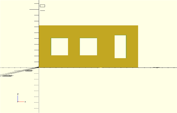
The first thing I did was look at my layout in openSCAD. Here is the code:

top(false, false);


module top(bExploded, bCutView){


    lapDepth = 0.375;

    topOverHang =1.5; // Overhang for front of top shelf

    fanSize=3;

    outletW =2;

    outletH=4;

// Back

rotate(bCutView ? [90,0,0] : [0,0,0])

difference(){

cube([17,.75,7.25]);

translate([13,0,1.625]) cube([outletW,.75,outletH ]);

translate([2,0,2.125]) cube([fanSize,.75,fanSize]);   

translate([7,0,2.125]) cube([fanSize,.75,fanSize]);  


}


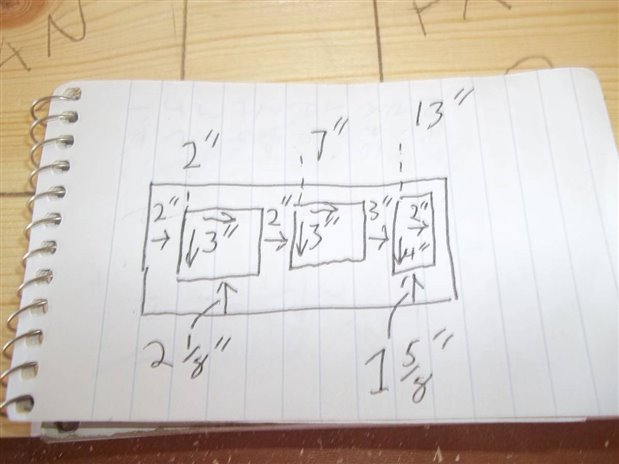
I then figured the locations of my cuts and wrote them on a notepad. I could have printed them, but one is 10 times more likely to remember something that they write in notes so I went old school:


image


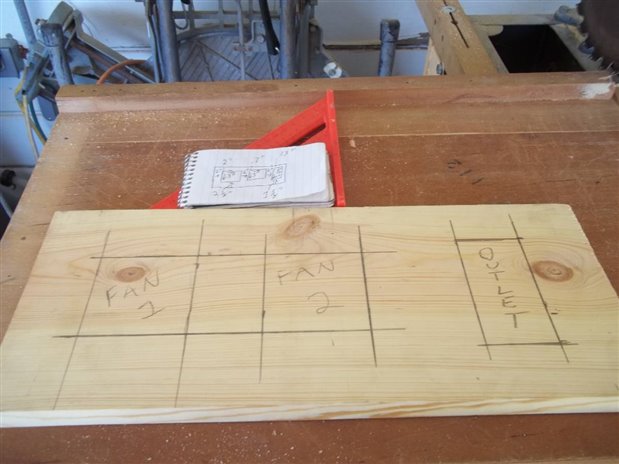
Then I used my trusty speed square to mark my material:

image


Then I clamped it up and broke out my drill and jig saw:

image


And checked my hole sizes along the way:

image

If you have a CNC router, this step will be much easier. A DIY CNC router is in the works for me as I got several scanners and printers in a load of electronic scrap. I also have a 6 amp reciprocating saw motor to use, but I have several other projects to complete before I can build mine.  Most importantly, I need to get some walls up on my carport to house it....but I digress.....


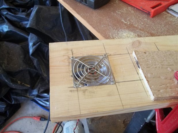
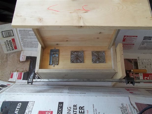
Next, I dry fitted the accessories and clamped it up. I know the fan on the left is slightly crooked, but it is close enough to fix with my spiral saw when I cut the holes for the wiring. It is less than 1/8" high on the right side and the left corner, which is low, lines up with the center fan. The jaggedness will be covered by the plastic trim that will also serve to help keep the fans mounted.

image


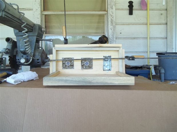
To clamp this up I really needed 4 furniture clamps but I only had 2, so I had to cheat a little bit and squeeze some glue in and re-clamp some points. It is also helpful if you have a space that is big enough to hold the entire footprint of this project when clamping so the base can be clamped to the top as level as possible. I will add adjusting feet to mine to make up for the slight amount that mine is not in level.


image


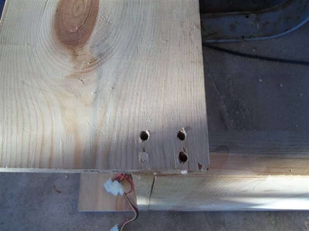
I also added 4 dowel joints to connect the top to the base for extra strength. I didn't have a drill press so to get my holes drilled as straight as possible I used a small nail to press into the wood at the point where I wanted to drill. I drilled a pilot hole with a tiny bit, then I drilled it out with my 1/4" bit (the size of the dowels). Then I dipped my dowels in Gorilla Glue and taped them in with a rubber mallet:

image


image


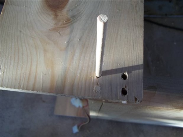
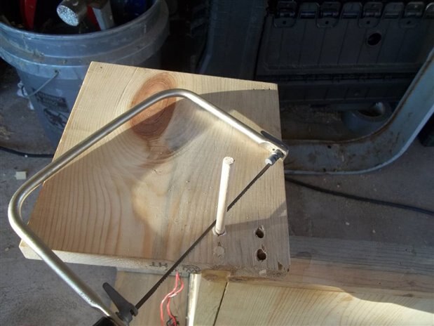
When the dowel was in place, I cut them with a coping saw and moved on to the next hole:


image


Then I sanded out the joints so they look smooth.


Since I used a 2"X 4" outlet box, I can just simply drop an AC with USB type outlet in for power, but I don't plan to be so easy on myself. I am going to fix a small power supply that came with a USB hard drive connector for my 12 and 5 VDC rails and use a couple of outlets for my AC line for my soldering guns. In the future I might add a Hakko circuit to power some homemade guns to this, but it should do like it is for now.


The next phase is the design and printing of the printed plastic, so until next time, happy tinkering.....

  • Sign in to reply
element14 Community

element14 is the first online community specifically for engineers. Connect with your peers and get expert answers to your questions.

  • Members
  • Learn
  • Technologies
  • Challenges & Projects
  • Products
  • Store
  • About Us
  • Feedback & Support
  • FAQs
  • Terms of Use
  • Privacy Policy
  • Legal and Copyright Notices
  • Sitemap
  • Cookies

An Avnet Company © 2023 Premier Farnell Limited. All Rights Reserved.

Premier Farnell Ltd, registered in England and Wales (no 00876412), registered office: Farnell House, Forge Lane, Leeds LS12 2NE.

ICP 备案号 10220084.

Follow element14

  • X
  • Facebook
  • linkedin
  • YouTube