


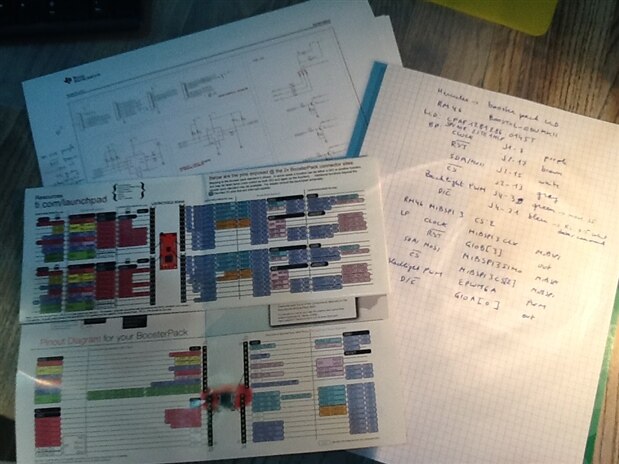
| The Educational BoosterPack MK II, the Texas Instruments kit with loads of goodies. Who hasn't seen it? I have one. And I have plans with it. I want to turn it into the user interface for a safety features test bed for Hercules micro controllers.
This time I ported Rei VILO's LCD_screen Library Suite to the Hercules SPI api. I have the essentials ported. The screen is not working though. That's OK. I learn when things aren't working straight away. And I have enough material to prove that I'm on the right path.
This blog is about the porting exercise. The next one will cover my troubleshooting efforts. |
How Do I Approach Porting
Oliver's LCD library is Energia based. Arduino savvy designers - certainly those that have written libraries for the platform - will recognize the code, because Energia, just like the Arduino hemisphere, is Wire based.
There are a number of facets I like about his work. It's c++ - how wish I could design object oriented firmware for the Hercules.
And he uses a good level of abstraction. His base class is an abstract LCD library, agnostic of the real hardware. That one knows what a screen is, and the typical drawing instructions.
His second layer adds the skill to write text on that screen. It's still hardware independent - but muich of the non-hardware stuff is implemented at that time.
His lowest level class, Screen_HX8353E, is where the hardware dependent methods are implemented. This one knows the coordinates, the SPI commands and all those other things that drive the physical LCD.

And then I threw all of that away. No, I didn't. I gave up on the objects (I have to, this isn't c++). And I gave up on the abstraction layers.
But I kept the spirit of the abstraction in my comments. For each item that I've ported, I commented the class I stole it from.
In due time, I can reintroduce the abstractions. Even c allows you to do a decent job there. But for now, I focused on getting the essentials ported.
When I port, I use the compiler as my friend. I copy over the essentials of original source code into my project, and keep compiling until the build succeeds  .
.
In this case, I copied over the initialization code - the part where attributes are set and the screen is put in an initial clean state.
That includes setting the screen coordinates, and calling several SPI commands to get a nice blank screen.
Everyone has their own style of porting. Some do a full analysis of the source, others may have different ways of working.
What works best for me is to copy the core code and branching out from there.
I integrate the code in my project skeleton and comment it out fully. Then I do a first compilation. That has to pass.
Then I uncomment the first manageable block of code. I recompile again and analyze the error log.
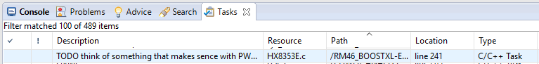
For each function call that's missing, I create a stub, and place a //todo comment in the implementation. My IDE's task module keeps track of these to-dos.
Then i fix the compilation errors, one by one. I scan the error log for the obvious ones first, and fix those.
I continue until there are no compilation errors left.
Then I uncomment some more code, and repeat the exercise until the core framework compiles.
At that moment, I copy over the implementation of the first skeleton function. And again, I do the same exercise.
Any new function gets a new skeleton, any compile error gets fixed.
It's almost a recursive exercise. You can see the work here - I always leave the original code commented until my library is ready for release.
/**
 * this is the functionality of the energia lib constructors
 */
void screenInit() {
    // LCD_screen::LCD_screen()
    _fontSize       = 0;
    _fontSolid      = true;
    _penSolid       = false;
    _flagRead       = false;
    _flagStorage    = false;


    // LCD_screen_font::LCD_screen_font()
    // empty


    // Screen_HX8353E::Screen_HX8353E()
    _portReset = gioPORTB;
    _pinReset = 3;
    _portDataCommand = gioPORTA;
    _pinDataCommand = 0;


    // I could move this to Begin(), because I'm doing more than initialising local variables
    gioInit();
    etpwmInit();


}


void screenBegin() {
    // Screen_HX8353E::begin()


//    SPI.begin();
//
//    SPI.setClockDivider(SPI_CLOCK_DIV2);
/*
 * this is a 8MHz speed (16MHz Arduino speed/2)
 * In HalCoGen, on data format 0, I defined Baudrate 8000 kHz
 */
//    SPI.setBitOrder(MSBFIRST);
//    SPI.setDataMode(SPI_MODE0);
    mibspiInit();


//    if (_pinReset!=0) pinMode(_pinReset, OUTPUT); // done in HALCoGen
//    if (_pinBacklight!=0) pinMode(_pinBacklight, OUTPUT); // done in HALCoGen
//    pinMode(_pinDataCommand, OUTPUT); // done in HALCoGen
//    pinMode(_pinChipSelect, OUTPUT); // done in HALCoGen
//    if (_pinBacklight!=0) digitalWrite(_pinBacklight, HIGH); // done in HALCoGen
    etpwmStartTBCLK();


//    if (_pinReset!=0) digitalWrite(_pinReset, 1);
//    delay(100);
//    if (_pinReset!=0) digitalWrite(_pinReset, 0);
//    delay(50);
//    if (_pinReset!=0) digitalWrite(_pinReset, 1);
//    delay(120);
    gioSetBit(_portReset, _pinReset, 1);
    delay(100);
    gioSetBit(_portReset, _pinReset, 0);
    delay(50);
    gioSetBit(_portReset, _pinReset, 1);
    delay(120);
//    _writeCommand(HX8353E_SWRESET);
//    delay(150);
//    _writeCommand(HX8353E_SLPOUT);
//    delay(200);
    _writeCommand(HX8353E_SWRESET);
    delay(150);
    _writeCommand(HX8353E_SLPOUT);
    delay(200);


//    _writeRegister(HX8353E_GAMSET, 0x04);
//    _writeCommand(HX8353E_SETPWCTR);
    _writeRegister(HX8353E_GAMSET, 0x04);
    _writeCommand(HX8353E_SETPWCTR);
//    _writeData88(0x0A, 0x14);
//    _writeCommand(HX8353E_SETSTBA);
//    _writeData88(0x0A, 0x00);
//    _writeRegister(HX8353E_COLMOD, 0x05);
//    delay(10);
    _writeData88(0x0A, 0x14);
    _writeCommand(HX8353E_SETSTBA);
    _writeData88(0x0A, 0x00);
    _writeRegister(HX8353E_COLMOD, 0x05);
    delay(10);


//    _writeRegister(HX8353E_MADCTL, HX8353E_MADCTL_RGB);
//    _writeCommand(HX8353E_CASET);
//    _writeData8888(0x00, 0x00, 0x00, 0x79);
//    _writeCommand(HX8353E_RASET);
//    _writeData8888(0x00, 0x00, 0x00, 0x79);
//    _writeCommand(HX8353E_NORON);
//    delay(10);


    _writeRegister(HX8353E_MADCTL, HX8353E_MADCTL_RGB);
    _writeCommand(HX8353E_CASET);
    _writeData8888(0x00, 0x00, 0x00, 0x79);
    _writeCommand(HX8353E_RASET);
    _writeData8888(0x00, 0x00, 0x00, 0x79);
    _writeCommand(HX8353E_NORON);
    delay(10);


//    _writeCommand(HX8353E_DISPON);
//    delay(120);
//    _writeCommand(HX8353E_RAMWR);


    _writeCommand(HX8353E_DISPON);
    delay(120);
    _writeCommand(HX8353E_RAMWR);


    //    setBacklight(true);
    //    setOrientation(0);
    //    _screenWidth  = HX8353E_WIDTH;
    //    _screenHeigth = HX8353E_HEIGHT;
    //    _penSolid  = false;
    //    _fontSolid = true;
    //    _flagRead  = false;
    setBacklight(true);
    setOrientation(0);
    _screenWidth  = HX8353E_WIDTH;
    _screenHeigth = HX8353E_HEIGHT;
    _penSolid  = false;
    _fontSolid = true;
    _flagRead  = false;
    clear(blackColour);


    _setPoint(5, 5, greenColour);
    _setPoint(6, 5, greenColour);
    _setPoint(7, 5, greenColour);
    _setPoint(8, 5, greenColour);
    _setPoint(9, 5, greenColour);
    _setPoint(10, 5, greenColour);
    _setPoint(11, 5, greenColour);
    _setPoint(11, 5, greenColour);
    _setPoint(12, 5, greenColour);
    _setPoint(13, 5, greenColour);


}
The typical fixes are to convert the code to the destination controller - in this case a 32-bit ARM, and to migrate the peripheral dependent code.
For the LCD library, that means porting the SPI logic to the Hercules MIBSPI API. Not difficult.
The whole exercise of porting the initialization code and all the functions that are used in that, took me about 4 hours. That includes baking and eating one pizza.
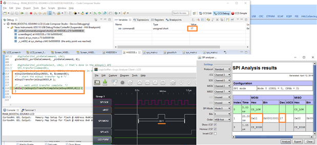
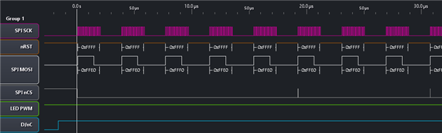
And the code kind of works. It executes without errors and I see the results on the logic analyzer.
Unfortunately* it doesn't work. The display doesn't react on the code. I was expecting to see a yellow square and a green line on the display, but it does nothing.
* That's OK. I have a sound starting point that allows me to get this working. And I have a working set-up too. I can always execute the test on an MSP430 LaunchPad here, and probe the traffic with the analyzer.
That will allow me to compare what I have done with how it should be done. A luxury situation.
Since I published this blog earlier then expected (I planned to save it as draft, but pressed the wrong button) I'll fork off the next section to part 4.
It 'll contain captures of SPI traffic going to the LCD. A trace here to prove that I have traffic 
| Related Blog |
|---|
| Educational BoosterPack and Hercules LaunchPad: LCD Driver - Part 1 |
| Part 2: Logic Analyzer and LCD Backlight |
| Part 3: SPI Works |
| Part 4: Everything Works |

