


ELEC2645 - Embedded Systems Project - 'Sensor-matic!'
The aim of the project is to create an interface between a distance and a temperature sensor and an LCD screen.
Project Aims and Objectives
Aims:
- To develop a small, portable battery-powered distance/temperature sensor.
- To read the sensor outputs frequently.
- Display the sensors outputs on a Nokia 5110 LCD screen.
- Provide a visual representations of the distance/temperature on the display.
- Use an options menu to toggle various aspects of the hardware functionality (i.e. toggle the use of LEDs and sound).
- Maximise the battery life by using as little power as possible.
Objectives:
- The battery will be a PP3 9 V battery which is mounted onto the PCB.
- The sensors will take 10 readings every second and average to minimise errors.
- A timer will be used so that measurements are taken at intervals.
- The Nokia 5110 library will be imported and used to display the value of the screen at every interval.
- ‘IF Statements’ will be used to display the visual representation of the distance.
- A 10 K Potentiometer will vary the selection of the options menu.
- LEDs will light up depending on the distance (Green àààà
- A Piezo will buzz on each iteration and buzz faster at increasing distance.
- An efficient switching regulator will be used to minimise power-usage.
- Sleep Modes will be used to save power.
Project Constraints/Components
Main Components:
- Ultrasonic Distance Sensor (SRF02).
- Temperature Sensor (TMP102).
- Nokia 5110 LCD Display.
- Powered by PCB-Mounted 9 V Battery (PP3).
- Stepped Down using 9-t0-5 V Buck Converter (MC34062 & Associated Components).
- Two-Layer PCB Board (100 mm by 80 mm).
Electronic Components:
- 3mm LEDs (1x Red, 1x Green, 1x Yellow).
- 1 kΩ Resistors (1206 Surface-Mount Package).
- 2x Push Buttons – Change Menu Display & Invert Colour.
- 1x Slide Switch (SPDT) – Power Supply Control.
- Piezo Buzzer – Sounds at Regular Intervals.
- 10 K Potentiometer – Change Menu Selection.
Project Specification
Specification:
- The device will be powered by a single 9 V battery.
- A 9 V-to-5 V Switching Regulator (MC34063) will be used to step-down the voltage.
- There will be a red LED in parallel with the switching regulator to indicate powers on.
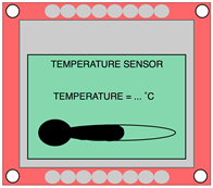
- A TMP102 Temperature Sensor will be used.
- A SRF02 Distance Sensor will be used.
- A Nokia 5110 LCD will be used to display the data.
- Digital buttons will be used to navigate forward and backward through screens
- A potentiometer will be used to vary the menu option that is selected.
- A reading will be taken every second – with an average taken every 10 seconds.
- The display will show a bar which fills in as the distance/temperature increases.
- The visual alert will be a red/green/yellow LEDs (solid colour) and when the distance/temperature is very low/high (respectively) all LEDs flash together (2 Hz).
- A 2 kHz tone will be generated by driving the piezo with a PWM waveform.
System Architecture Block Diagram:

User Interaction
PCB Design:
- Keep inputs and outputs around the edges of the PCB – easier user interaction.
- Put the Screen in the middle of the PCB and make it unobstructed
- Include sensors at the edges of PCB (especially SRF02).
- The distance sensor needs to be above the screen and facing out so the user can hold it in front of them to measure a distance.
- B1 and B2 are simple buttons to navigate backward and forward (respectively) between the menu screens.
- The pot is located at the bottom of the board in its own space so it can be adjusted.
- The switching regulator will be underneath the screen.
- The switch, SW and LED1 are power-related components. The switch is used to control the power and the LED is an indicator to show it is on.
- LEDs: LEDR, LEDY and LEDG are used as visual indicators.
- The reason the vertical edges of the PCB are kept fairly clear is because the mbed has to be soldered on the underside as well as a battery pack.
- NB: The whole PCB will be handheld in a portrait orientation however it was rotated into a landscape position to save space.

Presentation on Display:
- A series of menus will be used.
- Due to screen size limitations, the maximum number of options per menu will be two if the screen is to appear aesthetically pleasing.
- This means that 3 menus are needed:
- 1st = Sensors or Options
- 2nd = Distance or Temperature (Sensors)
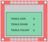
- 3rd = Various Options (i.e. Toggling Sound/LEDs)
- Each menu besides the options menu will have a title.
- Depending on how crowded the page is, a border may be added around the page.
- Welcome Screen:

- Initial Menu:

- Sensor and Options Menu:

- Distance and Temperature Screens

- The diagram below describes the navigation through the menu screens starting from the top left.
- The square at the side of each option appear when the specific option is selected and each arrow corresponds to the next screen that is displayed.
- When the back button is pressed, the sequence moves back to the previous screen.


