


Welcome to Jefferson's Blog
About me : https://uk.linkedin.com/in/jeffersonpiaunsanchez
for more follow me on my page for more updates. https://www.facebook.com/MrJefferson105/
Youtube channel : https://www.youtube.com/user/MrJefferson105
Game of life Year one : https://www.youtube.com/watch?v=PqFYzxFdhYU
The structure of my blog will be the following:
- Introduction
- Choosing Project Idea
- Hardware description
- Software Description
- Testing
- Conclusion
1- Introduction :
The aim of this blog is to help other students who are starting or for those who would like to get any ideas for future projects .The aim of my project is to make a arcade game such as Snake , Battle ships , Avoider game , ping pong etc. The game will be made using a online compiler which allows me to edit and compile the code to the micro-controller that would be used . Also in order to be able to see what is happening on the game, a screen will be used to display the game and other information such as rules etc.
Before starting to design my project I had to learn how to interact with the Lcd and any other components in other to help me understand . This was done in a module called 2645 Embedded Systems , where student gets taught how to code and interact with different modules and components.
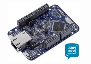
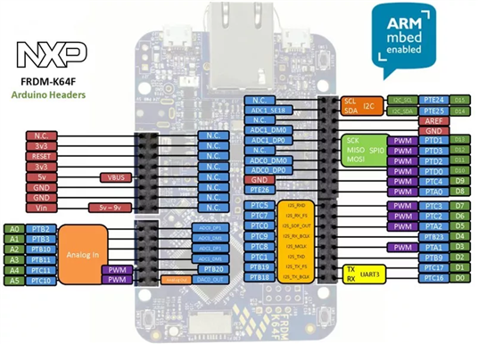
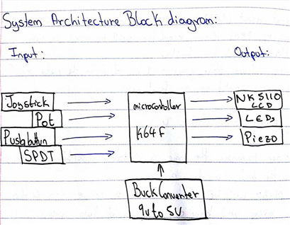
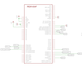
- FRDM K64F Micro-controller
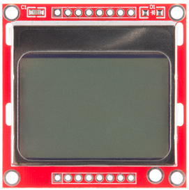
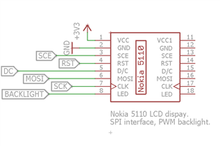
- Nokia 5110 LCD display
This is a simple LCD that can have a lot of applications since it is very versatile to work with.
2- Choosing Project Idea
In order to come up with an idea that could be a potential solution for the problem given , first of all several ideas were written down along side the pros and cos of each one , after all this a solution was chosen against the following points :
- Complexity : Software and Hardware
- Constrains : The amount of components that we are aloud to use , could be limiting factor, as to how interactivef the project can become .
- Understanding : Organisation of code , eg , header files ,libraries etc.
- Time Constrain : How long will it take to complete ? Will it be able to be completed by the deadline given ?
- Snake : Moderate level , we have learnt about how a joy stick works , sound for every time the snake eats the food , perhaps with a score.
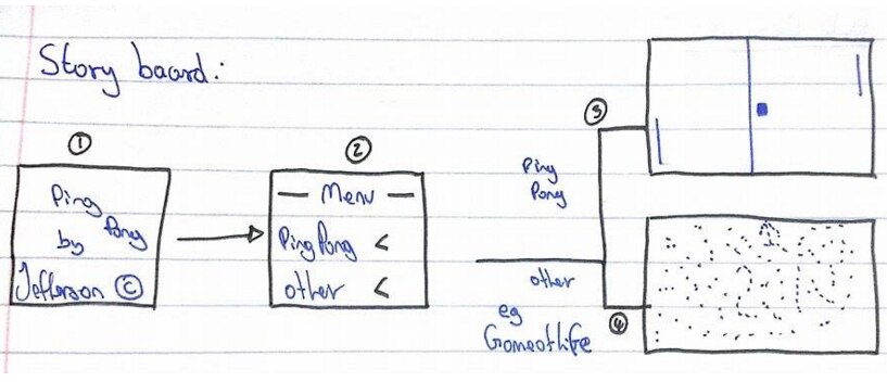
- Ping Pong : Moderate to Intermediate Level , using a joy stick to move the paddle up and down in either side of the screen , different speed maybe , Ai : probably no . Multiplayer: Yes, make one player and duplicate the code for the two player game .Menu with two options.
- Etch sketch : moderate , this is the beginning of snake , with a menu , a few buttons to pause and re-start game. and provide examples for the user to understand the rules etc .
- Avoider Game : Moderate to Intermediate Level , The plan would be to have some kind of obstacles from the top of the screen falling and a character will avoid this obstacles to prevent it form dying, include a score for for the amount of obstacles avoided . etc
Chosen Idea :
In order to choose the ideal project, it had to comply within the four point talked about before .
Project chosen : Ping Pong
- Complexity :
Hardware
The hardware required to make only the game is a LCD , K64F (micro controller), Joystick or Potenciometers. I think that the connections for this components would be easy enough and will not take long to organise the layout and to colour code the connections to the micro controller . Since the project has to be powered by a 9 v battery this means that a Buck converter will be used to convert the 9 volts to 5 volts that the micro-controller requires in order to work.
Software
The algorithm required to make the game work is not easy but because I would like to push myself a bit more . Also this means that in worst case scenario a simpler game should be done before starting starting the main one .
simpler game will include ; menu --> the game of life rules , sounds and several more extras to make the game a bit more interactive for the user .
- Constrains
This project does not have that many constrains since the amount of components that are required for the program are very few .
- Joystick
- Nokia 5110 LCD display.
- TMP102 Temperature Sensor.
- 4 GB microSD card.
- on-board accelerometer/magnetometer.
- The project must be powered by a PCB-mounted 9 V battery .
- 9-to-5 V Buck converter must be built (MC34062 with associated components calculations ).
- PCB board is limited to a size of 100 mm by 80 mm.
- General components:
- LED's (red, green, yellow)
- 1 K-ohm resistors
- Push buttons
- Slide switch
- Piezo buzzer
- 10 K potentiometers
- Understanding :
In order to help me with the organisation of the of the code I will learn how to use header files and libraries to be able to trouble shoot problem that could be encounter later on in the prototyping stage.
(I have included an example code at as an attachment ) this is for anyone who would like to understand what is happening .
3- Hardware Description
For the hardware the main consideration is to think ahead in terms of will all the components that will be used for this project fit into the 100 x 80 mm PCB , this will allow me to used fewer components and check is it will physically fit all the requirements .
- Specification :
The aim of this project is to create an arcade game such as Ping Pong in order to accomplish this several components will be used such as:
- The device will be powered by a single 9 V battery.
- A 9 V-to-5 V switching regulator (MC34063) will be used to step-down the voltage.
- A Nokia 5110 LCD will be used to display the Ping Pong Game and a menu with two options.
- A visual alert (LEDs) to show the movement of the X and Y potentiometers.
- A tone will be generated by driving the piezo.
- A slide switch (SPDT) will be used to power on the board.
- Push button will be used to reset the game.
- A PCB design will be done to place all the components neatly and making sure the whole project is also fully portable.
- A back up 7805 linear regulator will be used in case the main switching regulator fails.
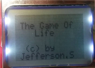
- If time allows other games will be added to the menu e.g. Game of life which was created on my first year.
The objectives of the product would be:
- In order to make the game a library may possibly be implemented for the ball and the paddle.
- The piezo will be used to make a noise when either player wins.
- The menu will have a minimum of two options.
- An efficient switching regulator will be used.
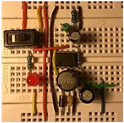
> Prototype : Breadboard and jumper wires.
For this project I will be using a breadboard to help me with the lay out of my components and to trouble shoot several things before designing my PCB .
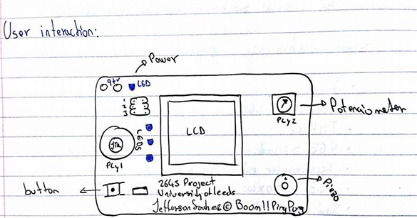
These are some pictures of the the full hardware in a nice portable and compact manner .
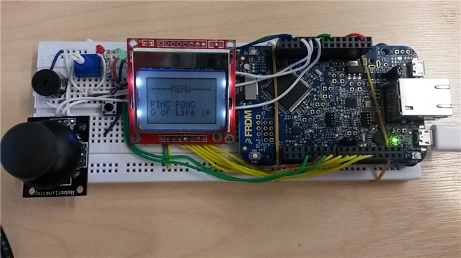
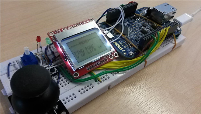
The layout of of the hardware will be described from left to right .
The joy stick is mainly used as an input for ping pong .
The Blue potenciometer is used to make the game of life run faster or slower depending how the user wants .
The button is used to select on the menu .
The Red and Green leds are used to show the direction of the joystick on the menu and show to the user what game has been selected .
The LCD is used to display all the information of the games and menu .
The micro-controller is used to run the code accordingly to the inputs given.
The specification for the hardware side has been met .
Possible extras :
Try to use the SD card to save information .
Try to understand how bit maps work .
Block Diagram :
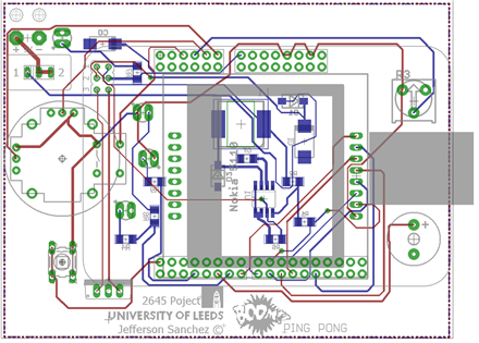
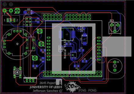
> PCB design : Program used Eagle.
The first thing to start with this part of the project was by learning and understanding the program to be able to make my own PCB , in order to do this I followed the tutorial done by Dr Evans but also I followed another Electrical Engineer called Jeremy Blum who happens to be sponsored by element 14 .
Here are a list of the very well detail tutorials to get to understand the program fully.
Tutorial 1 for Eagle: Schematic Desing https://www.youtube.com/watch?v=1AXwjZoyNno
Tutorial 2 for Eagle: Printed Circuit Board Layout https://www.youtube.com/watch?v=CCTs0mNXY24&nohtml5=False
Tutorial 3 for Eagle: CAM Output and DFM https://www.youtube.com/watch?v=oId-h6AeXXE&nohtml5=False
The free version of Eagle will be used to create the PCB . In order to create the PCB certain things were put in place.
When prototyping any circuit, breadboards are ideal since it allows the user to connect the components without having to solder the components to each other.
For a more professional looking circuit diagram a Printed Circuit Board (PCB) can be used , To make a PCB which is usually custom made using a computer program for this specific purpose.
As we can see in the picture below the blue tracks represent ground (GND) and the red tracks represent +3.3v , some signal wires were made with thickness of 0.0016 and the power track you will notice that are thicker with a thickness of 0.0032.
> Schematic :
Before designing a PCB a schematic is the first thing that has to be made in order to see the connections later on when it comes to do the routing for the PCB as shown above . The way the connections are made on the software is in blocks , this means that each sensor or module will have its corresponding connections properly named but it will help preventing wires from getting in the user way when checking the connections on the screen interface.
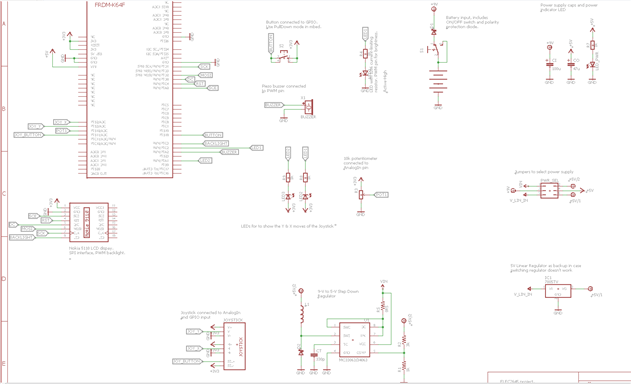
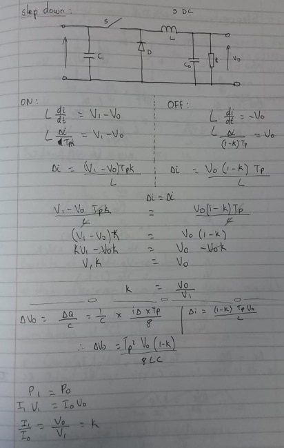
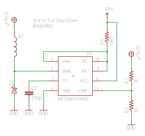
Buck converter design :
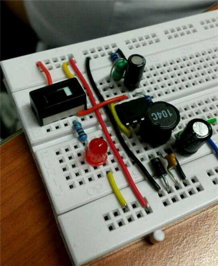
A 9 V-to-5 V switching regulator (MC34063) will be used to step-down the voltage. As you can see below the full buck converter assemble in a breadboard .
In order to select the right components values calculation using the following formulas were made :
For more information on how switching regulators work and how to make one here is a link : https://www.youtube.com/watch?v=CPvA-uS0dNY
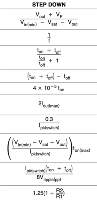
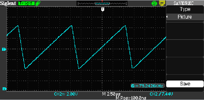
Testing to make sure that the components match the calculations as shown on the pictures below Vin = 9v and Vout = 5v , the five volts will be used to power the micro-controller.
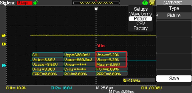
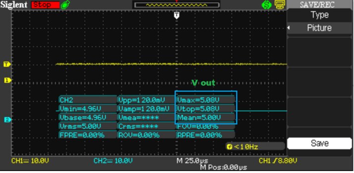
Pin 2 wave form on the IC Pin 3 wave form on the IC
Breadboard layout
4 - Software Description
In order to create the code a Mbed Online compiler will be used : https://developer.mbed.org/
The board used for this years project is the FRDM K64F https://developer.mbed.org/platforms/FRDM-K64F/
- The way I have approached this project is :
I have used some of the code provided by Dr Evans to read the joystick values to state direction e.g UP , Down , this is essential for the menu since I am only using two options the this will be enough.
Pong will be registered when the joystick is pushed UP and the other games option will be registered when joystick is pushed DOWN .
The joystick gives values such as 0.33 and 0.66 when pushed up or down , I am using some if statements to check , eg values bigger that 0.66 will be considered as a 1 and values equal to 0.33 or less will be considered to be a 0 . This allows me to use 1 and 0 as the values that my menu is looking for to change the from game to game .
In order to make my menu I think using cases to do so would be a good idea to approach the problem.
A push button is also used to select the option so a switch function should be used to do so .
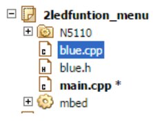
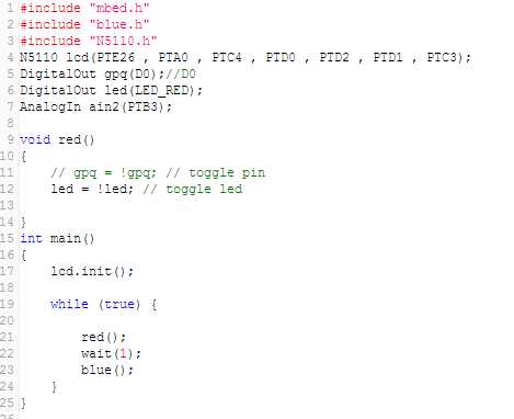
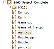
>Code organisation :
In order to not get confused as to what code is what when It comes to join all three codes , header files will be used . e.g main.cpp , ball . cpp , ball.h etc also Doxygen will be used to document the code to make it look more professional.
> Code : > menu > pong
> Other games
Pictures
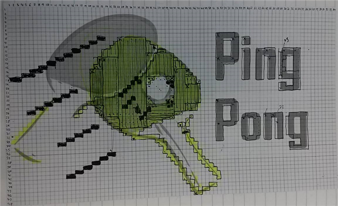
In order to make all the pictures for my games a method of finding out what pixels represent what was needed in order to switch them on and off on the 5110 display.
As you can see above the whole screen is effectively a grid of 48 x 84 , so a excel document was created with these dimensions and a picture of a paddle with a ball was drawn behind the grid to allow me to see the squares of the grid. After all this was completed, in order to prevent myself from making the whole image pixel by pixel , the image was divided into rectangles and squares where possible by doing it this was it can be argued that this method is time consuming and you are not wrong but by splitting the image up the job became a lot simpler to do and the image of the paddle with the ball and the words only took me twenty minutes to do .
A second method was considered which was using bit maps which allowed me to do it faster but I haven't been able to understand how the properly work and it is something that can be done on a future.
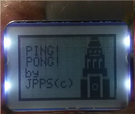
Ping pong picture :
Text Method:
In order to display text on the display , Dr Evans library for the Nokia 5110 will be used along with some of the example code provided within the library too . I believe that text it is a very important thing to have since I will be using it to create my menu and also to give instruction to the user playing the games.
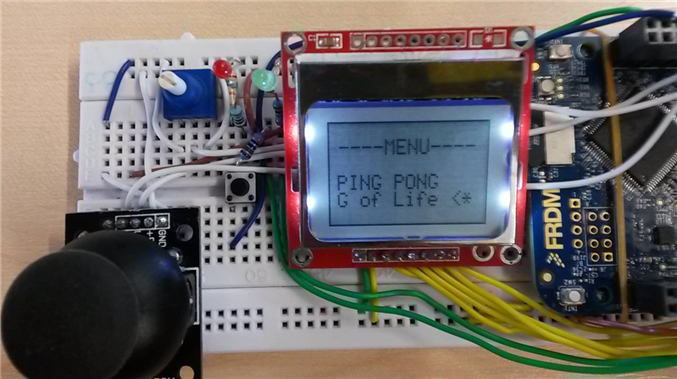
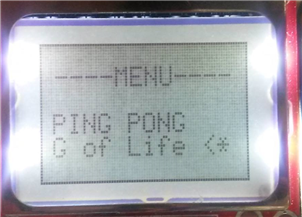
The menu layout will consist of three rows and 1 row for the title.
Menu
Ping pong [.]
G of life [*]
Credits [..]
Pseudocode:
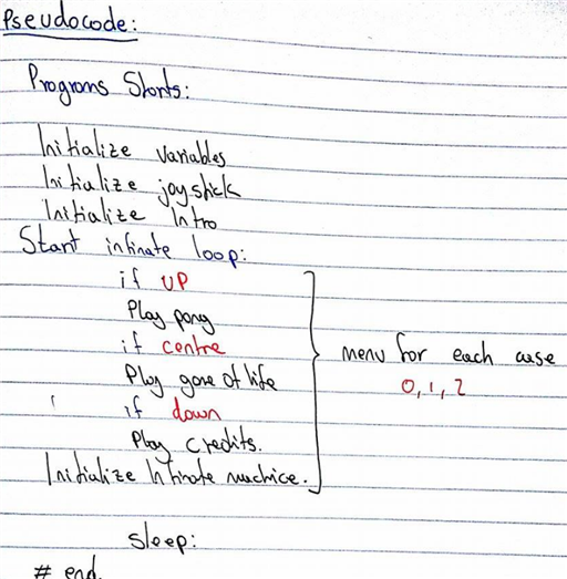
On the code ,the menu will be controlled by using the joystick , in order to select and movement of the dot [.] or [*] cases will be used . Problems that where encounter when prototyping the menu were as follows :
Problem:
- Updating : At the beginning of the the prototyping stage the substitute for the joystick was two 10 KΩ Potenciometers , as you may know this devices will give a constant value depending where the user wants them . It the potenciometer is turned 180 degrees to the left the value read was 0.33 and it is turned to the opposite direction the value was 0.66 , this values where perfecty fine and the menu moved up and down without any problems . The actual problem began when the actual joystick was replaced by the joystick ,this device has a spring or something similar that allows the user to push it up and it will go back to the centre position always and as you could understand this was causing a lot of trouble for my menu to work properly.
Solution : After trying different things the best solution for this problem was to make a state machine for the cases, meaning that this will allow the user to move up and the dot [.] or [*] will stay in that position regardless of the joystick going back to its centre position.
Game of life flow chart:
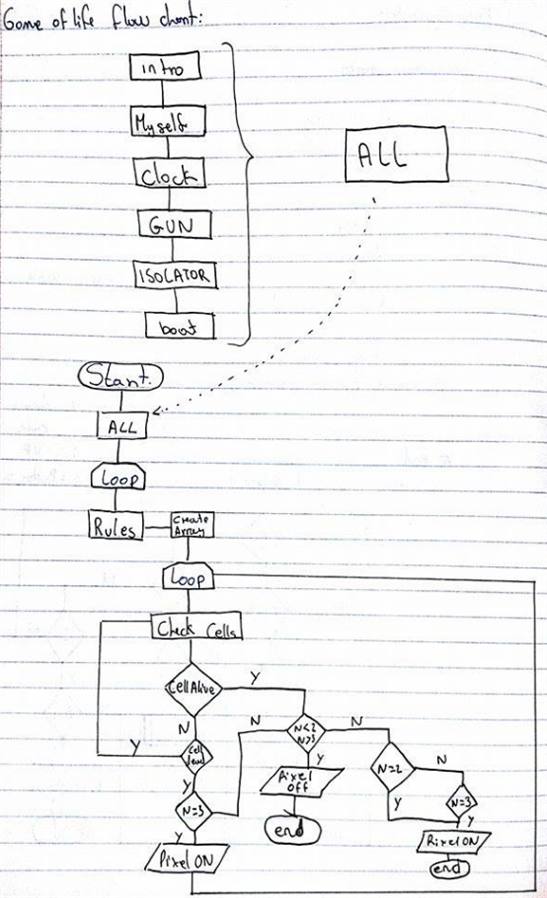
The game of life was created last year for Elec 1620.
5- Testing :
Final project :
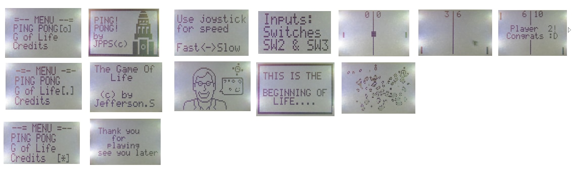
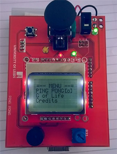
As we can see above the whole project is fully working in order to understand it an explanation of what happens from left to right is provided below.
- On the top left we can see that Pong has been selected (0), then the introduction to the game comes on along with some information for the user,
after this the game loads up and the user can start playing the game and As show in the last picture Player 2 has won with a score of 10.
- The middle row is the game of life being selected (.), then the introduction with some pictures and finally the game.
- The last row shows the credits being selected (*), then a message come along.
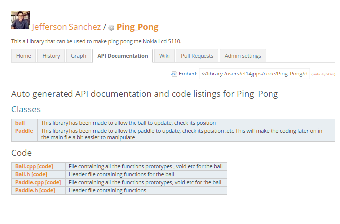
API documentation:
For all three Programs
Library : With the help of Example codes that was provided by Dr Evans.
Check project against specification
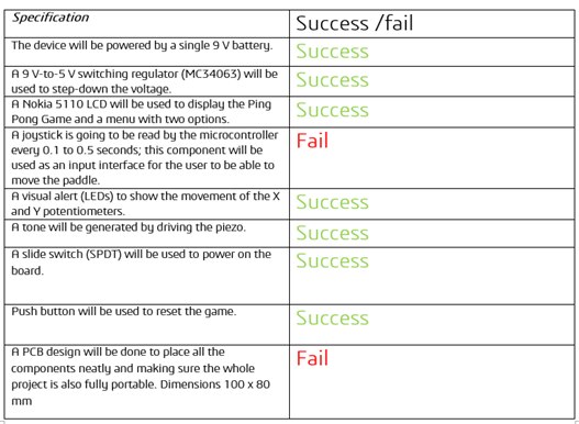

- Joystick = 0.25 ms
- The feedback for the PCB was " To messy " I think for future PCBs I will try to arrange my components into a more efficient manner.
- Pass rate of the project is 83.3%.
Final Product :
Conclusion :
In conclusion the product did not archived all the aims of the specification but the main one such as the code and the documentation were done to a good standard.
Improvements:
For my ping pong game an accelerometer can be used to move the paddles or to give some kind of effect to the ball when hit.
Expand the menu for more games
Be able to display more images using bit maps
A case for the final product could be done using a 3d modelling software
The PCB could be a bit smaller and compact to facilitate the grip of the game console.
Overall, I Believe that the project was successful because it has an 83.3% pass rate and the code flows smoothly without any problems. Perhaps if we are allowed more components the device could have been more interactive.
The creation of the project was a joy to do from the beginning right to the presentation.
Project Resources :
Library for ping pong :https://developer.mbed.org/users/el14jpps/code/Ping_Pong/#ef8d5a4464a3
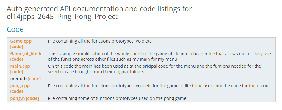
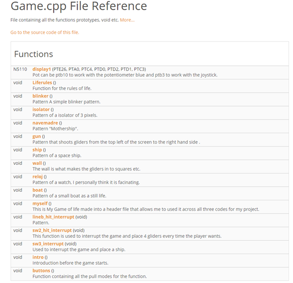
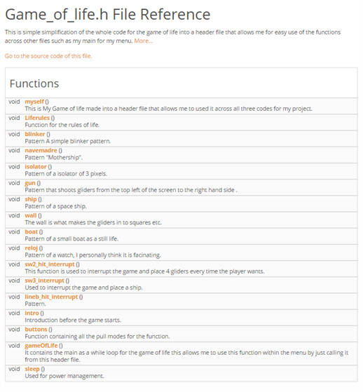
Code : https://developer.mbed.org/teams/ELEC2645-201516/code/el14jpps_2645_Ping_Pong_Project/docs/tip/
Power point : It is on the attachments below
This a brief lay out what has been done on it 
More information about any updates I do to the Software or to the Hardware of the project ..........
Please note that the code won't be provided on this blog, until the project has been submitted.
to be continued..........................
| Ping Pong.pptx | |


