element14 Community
element14 Community
    Register Log In
  • Site
  • Search
  • Log In Register
  • About Us
  • Community Hub
    Community Hub
    • What's New on element14
    • Feedback and Support
    • Benefits of Membership
    • Personal Blogs
    • Members Area
    • Achievement Levels
  • Learn
    Learn
    • Ask an Expert
    • eBooks
    • element14 presents
    • Learning Center
    • Tech Spotlight
    • STEM Academy
    • Webinars, Training and Events
    • Learning Groups
  • Technologies
    Technologies
    • 3D Printing
    • FPGA
    • Industrial Automation
    • Internet of Things
    • Power & Energy
    • Sensors
    • Technology Groups
  • Challenges & Projects
    Challenges & Projects
    • Design Challenges
    • element14 presents Projects
    • Project14
    • Arduino Projects
    • Raspberry Pi Projects
    • Project Groups
  • Products
    Products
    • Arduino
    • Avnet Boards Community
    • Dev Tools
    • Manufacturers
    • Multicomp Pro
    • Product Groups
    • Raspberry Pi
    • RoadTests & Reviews
  • Store
    Store
    • Visit Your Store
    • Choose another store...
      • Europe
      •  Austria (German)
      •  Belgium (Dutch, French)
      •  Bulgaria (Bulgarian)
      •  Czech Republic (Czech)
      •  Denmark (Danish)
      •  Estonia (Estonian)
      •  Finland (Finnish)
      •  France (French)
      •  Germany (German)
      •  Hungary (Hungarian)
      •  Ireland
      •  Israel
      •  Italy (Italian)
      •  Latvia (Latvian)
      •  
      •  Lithuania (Lithuanian)
      •  Netherlands (Dutch)
      •  Norway (Norwegian)
      •  Poland (Polish)
      •  Portugal (Portuguese)
      •  Romania (Romanian)
      •  Russia (Russian)
      •  Slovakia (Slovak)
      •  Slovenia (Slovenian)
      •  Spain (Spanish)
      •  Sweden (Swedish)
      •  Switzerland(German, French)
      •  Turkey (Turkish)
      •  United Kingdom
      • Asia Pacific
      •  Australia
      •  China
      •  Hong Kong
      •  India
      •  Korea (Korean)
      •  Malaysia
      •  New Zealand
      •  Philippines
      •  Singapore
      •  Taiwan
      •  Thailand (Thai)
      • Americas
      •  Brazil (Portuguese)
      •  Canada
      •  Mexico (Spanish)
      •  United States
      Can't find the country/region you're looking for? Visit our export site or find a local distributor.
  • Translate
  • Profile
  • Settings
Personal Blogs
  • Community Hub
  • More
Personal Blogs
Legacy Personal Blogs Exterminate! Experimenting with an SA602A
  • Blog
  • Documents
  • Mentions
  • Sub-Groups
  • Tags
  • More
  • Cancel
  • New
  • Share
  • More
  • Cancel
Group Actions
  • Group RSS
  • More
  • Cancel
Engagement
  • Author Author: jc2048
  • Date Created: 4 Mar 2020 10:46 PM Date Created
  • Views 2624 views
  • Likes 11 likes
  • Comments 5 comments
  • audio
  • mixer
  • modulation
  • analogue
  • sa602a
  • jc2048
  • dalek
Related
Recommended

Exterminate! Experimenting with an SA602A

jc2048
jc2048
4 Mar 2020

Introduction


In a recent thread here, I mentioned to dubbie that it might be possible to use the balanced modulator

in an RF mixer chip to create a Dalek sound effect. Later on, I discovered that I had a couple of them

[in the old DIL package, too], so I though I'd do a quick bit of hardware hacking and see how they manage

at audio frequencies. The mixer is based on a Gilbert cell, which will, of itself, work right down to dc,

but there is internal biasing of the transistors, which they don't show in any detail on the

datasheet, so I'll have to ac-couple the signals in.


Here's the equivalent circuit from the datasheet:


image


Pins 6 and 7 connect to the base and emitter of an internal transistor. In a radio, that would

connect to an external LC network to form a local oscillator. They show several example circuits on

the datasheet. The internal buffer then takes the signal, coming in on pin 6, to the mixing cell

without loading the external circuit too much. The transistor doesn't have to be used, instead it

would be possible to simply couple a signal straight into pin 6.


The signal input is on pins 1 and 2, to a differential pair. Above that the mixing with the signal

from the oscillator takes place and then the output is taken from pins 4 and 5. Although both input

and output are differential, there's no reason why I can't use it single-ended [differential would

be electrically quieter].


What to do for the oscillator? For a Dalek, I need a frequency of around 30Hz. Using an LC circuit,

the components get a little on the large side for a frequency that low, so I thought instead I'd

try a phase-shift oscillator. That will need some external gain - the internal follower doesn't

give us any voltage gain - so I'll need an external transistor as well.


Circuit


Here's the circuit I ended up with after a bit of fiddling around. It wasn't designed properly:

instead I chose reasonable-seeming values and hacked it about until it worked.


image


The signal comes from a signal generator [50 ohm]. I've terminated it with a 56R and coupled it to

the input pin with a 10uF electrolytic. At the other input I've placed a 10uF and 27R to ground, so

that the inputs roughly match. For the output, I'm just looking at the pin with the x10

oscilloscope probe.


Build


Here it is, built on my wonderful, whizzy, element14 breadboard [it used to advertise some video

channel, but I rebranded it]:


image


Here are the signals at the LO input pin [blue] and one of the output pins [yellow]. The oscillator

is oscillating just a fraction lower than the 30Hz I was trying for. The signal input [not

shown] from the generator is about 300Hz.


image


The oscillator is producing something a long way from a sinewave. Unfortunately, because of the ac

coupling, that then ends up off-centre and the modulation is lop-sided. But the multiplier is

working and performing the modulation. It's all rather noisy. The breadboard and my sloppy ground

layout probably don't help.


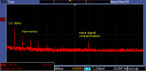
Here are some FFT plots to show the modulation better.


This is the LO ('local oscillator') at pin 6. The misshapen sinewave leads to a lot of harmonic

distortion. There's also some contamination from the input signal.


image


This is the signal going in. It's a much better sinewave, but still slightly messy [cheap

generator].


image


This is the resulting output signal. The LO is fairly well suppressed. The sidebands above and

below the signal, as a result of the modulation, are now evident.


image


If the LO were a perfect sinewave, we'd just see the pair 30Hz away from the signal, but here we

see the LO harmonics contributing as well. For a more complex waveform [voice, for instance] the

output would contain the original signal, the original shifted up in frequency by 30Hz, and the

original shifted down in frequency by 30Hz, all mixed together. That would sound like an ugly, very

extreme chorus effect, but quite inharmonic - any musical intervals would be by accident rather

than design: just what you want when you're an evil cyborg intent on galactic domination [or for

scaring young children hiding behind a sofa].


Update: 6th March


I was curious about the lop-sided modulation and wondered if what I said about being

able to use it single-ended, rather than differentially, was actually true. The

datasheet suggests it can be used like that, but at the same time they do seem to steer

you to differential coupling of the input and output.


It occured to me that one way to test that out would be to feed the same signal into the

LO input as the signal input. The multiplier should then give the square of the input.


For a sinewave going in, that would result in a sinewave of twice the frequency coming

out.


Here's the result [blue input, yellow output]


image


You can see we have the frequency doubling, but the waveform is, again, lopsided, so the

chip certainly doesn't balance very well internally.


Here are the two, differential, outputs on the 'scope together.


image


If I ask the 'scope to calculate the difference, like this


image


we see a sinewave, so it all works fairly well if we take the output

differentially.


As a further experiment, I added an external 100k pot to pull the biasing of the

transistor around. With a bit of adjustment, that then allowed me to get a reasonable

modulated signal out, but only on one or other of the outputs. This trace shows the

input (yellow) and an output (blue), with that output adjusted for best sinewave.


image


But if I look at both outputs together I see this. Pulling the biasing of the transistor

never results in both coming right simultaneously.


image


Conclusions


Although this was just a bit of hacking for fun, it was interesting to see how easy it was to

explore rf techniques, like modulation, at low frequencies using an inexpensive radio chip and a

modest oscilloscope with an FFT maths function.


For an actual effects unit, a variable, external oscillator might be a better choice than trying to

build something around the internal transistor. Some sort of gain control at the input and output

would also be useful (essential?): the differential amplifiers that make up the cell are only good

for a few hundred millivolts before signal limiting sets in but, at the same time, the levels need

to be kept reasonably high because of noise.


[1] SA602ASA602A

[2] https://www.nxp.com/products/rf/rf-mixers/low-power-fm-if-systems/double-balanced-mixer-and-oscillator:SA602AD


If you found this interesting and would like to see more blogs I've written, a list can be found

here: jc2048 Blog Index

  • Sign in to reply

Top Comments

  • shabaz
    shabaz over 5 years ago +4
    Hi Jon, Awesome work experimenting with the SA602 to accept a different frequency like this. It's nice to see how flexible these old chips are, to allow completely different projects that the manufacturer…
  • jc2048
    jc2048 over 5 years ago in reply to shabaz +4
    I've been thinking of trying some FM synthesis with my little Lattice FPGA board. Recently, I borrowed a textbook from the library about Fourier Analysis (by Kammler) and that has a chapter on music with…
  • genebren
    genebren over 5 years ago +3
    Very cool experiment. This is interesting subject, tied together with a very nice blog. Thanks for sharing!
  • jc2048
    jc2048 over 5 years ago in reply to dubbie

    I haven't tried it yet. I'll see if I can rig up something in the next few days. It's going to be embarassing if it doesn't sound like a Dalek.

    • Cancel
    • Vote Up +3 Vote Down
    • Sign in to reply
    • More
    • Cancel
  • dubbie
    dubbie over 5 years ago

    Jon,


    This all looks good fun and interesting. I could just about follow most of what you were doing although I think the reality of the analogue electronics a bit beyond me. It all seems a bit like trickery. I think I must be more a digital designer.


    Did it make any Dalek sounds?


    Dubbie

    • Cancel
    • Vote Up +2 Vote Down
    • Sign in to reply
    • More
    • Cancel
  • jc2048
    jc2048 over 5 years ago in reply to shabaz

    I've been thinking of trying some FM synthesis with my little Lattice FPGA board. Recently, I borrowed a textbook from the library about Fourier Analysis (by Kammler) and that has a chapter on music with a short section on FM synthesis (it was a bit odd to find the music stuff there, but I suppose it is quite intimately related to the theory he develops in the earlier part of the book and is probably a good way to keep students interested with a subject area that otherwise gets a bit maths heavy). He gives the parameters for the bell sound, that Chowning  and the people he worked with developed, which I'd like to have a play with. I hadn't thought of trying to do it with an analogue circuit.

    • Cancel
    • Vote Up +4 Vote Down
    • Sign in to reply
    • More
    • Cancel
  • shabaz
    shabaz over 5 years ago

    Hi Jon,


    Awesome work experimenting with the SA602 to accept a different frequency like this. It's nice to see how flexible these old chips are, to allow completely different projects that the manufacturer likely never expected : )

    When I started reading, I was initially wondering about using a soundcard for the spectral analysis, but then saw you got great results with the 'scope's built-in FFT capabilities.

    I tried experimenting a while ago with FM synthesis (it is written up here: Sound Synthesis and the Billion Dollar Paper  ) and I found it interesting learning how if certain harmonics are pulled out of the 'comb' (this naturally occurs with certain combinations of modulation index, modulation and carrier frequencies) then the sound changed a lot. I did it the boring way using a PC however, I didn't think at the time to try it with a radio chip!

    • Cancel
    • Vote Up +4 Vote Down
    • Sign in to reply
    • More
    • Cancel
  • genebren
    genebren over 5 years ago

    Very cool experiment. This is interesting subject, tied together with a very nice blog.


    Thanks for sharing!

    • Cancel
    • Vote Up +3 Vote Down
    • Sign in to reply
    • More
    • Cancel
element14 Community

element14 is the first online community specifically for engineers. Connect with your peers and get expert answers to your questions.

  • Members
  • Learn
  • Technologies
  • Challenges & Projects
  • Products
  • Store
  • About Us
  • Feedback & Support
  • FAQs
  • Terms of Use
  • Privacy Policy
  • Legal and Copyright Notices
  • Sitemap
  • Cookies

An Avnet Company © 2025 Premier Farnell Limited. All Rights Reserved.

Premier Farnell Ltd, registered in England and Wales (no 00876412), registered office: Farnell House, Forge Lane, Leeds LS12 2NE.

ICP 备案号 10220084.

Follow element14

  • X
  • Facebook
  • linkedin
  • YouTube