


About a week ago I bought myself a USB Programmer for Altera FPGAs and CPLDs. The place I bought
it from also had a small, simple CPLD board based on a Max II part for sale, so I got one of
those too. The pair came to around £16 and arrived the next day via ordinary letter post. It
seemed worth buying the CPLD card simply in order to quickly try out the programmer and convince
myself it worked, though I'm sure I can find some other uses for it.
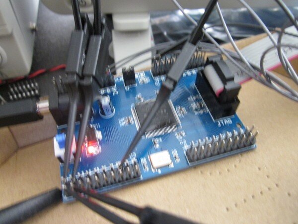
Here's what the CPLD board looks like
I'd previously installed Intel's Quartus software on my laptop to see if it would run ok [the
laptop is still running Windows 8.1]. When I originally did that I had only selected the Cyclone
devices, so as to make the download more manageable, but to use it with this board I now needed
to add the Max devices. Downloading the file was no trouble, but when I tried to install the
devices I couldn't do it. The entry on the Quartus 'Tools' menu for 'Install devices...' didn't
work.
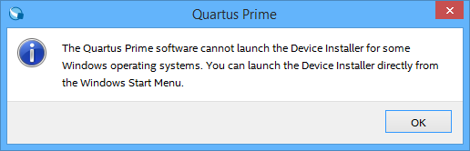
That wasn't very helpful because it didn't tell me the name of the executable to look for. After
a bit of searching, it turned out that the devices can be updated by running the Quartus setup
again. Fortuitously, I'd placed the file alongside the previously downloaded Quartus and Cyclone
devices files, so when the setup was run again it recognised the newly added device file and gave
me the option of updating the install.
Next hurdle was the USB. I plugged the programmer in and tried to install the driver. That failed
with an unhelpful error message that didn't give much of a clue as to what had gone wrong. It
turned out that the driver that comes with the current Lite version of Quartus that I'd
downloaded isn't signed and my Windows 8.1 rejects it [but with a vague 'there was an error'
message]. The simple solution, apparently, is to use an older version of the driver [the one that
did install is from 2009 and signed by Altera]. That worked and allows the programmer software to
see the USB programming cable.
I've not used Altera tools before, but it's very similar in style to other FPGA integrated design
environments that I've used [the old Xilinx Webpack ISE and Lattice's Diamond], so it wasn't too
hard to write a quick bit of VHDL to test the programmer. This code divides the board's 50MHz
clock by 50 million and then uses the resulting 1Hz-rate enable signal to enable counts of a 4-
bit binary counter.
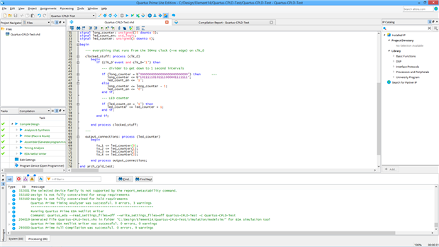
After I'd corrected the syntax errors, that programmed the board fine

It almost worked. After a bit of head scratching, I realised I'd selected the wrong pin for the
clock input when I was doing the pin assignment.
Here are the waveforms displayed on my oscilloscope.
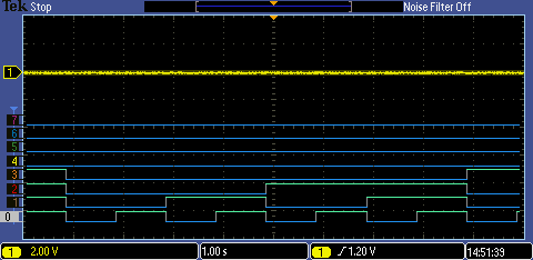
The reason for having it so slow is that originally I was going to light up some LEDs, but in the
end merely settled for showing the waveforms.
Top Comments