


Here is a project created to interface and explore how to access the SD-Card slot available onboard with K64F freedom board.
Before we start this project below are the pre-requisites:
- KDS software tool from Freescale
- FRDM-K64F Freedom development board
- Micro-SD-Card ( I am using 1GB)
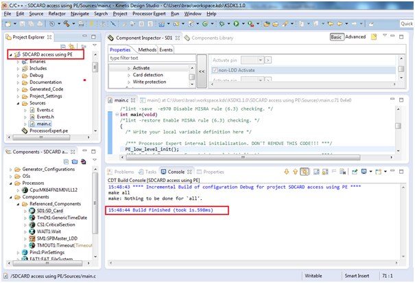
I have created a project by name “SDCARD access using PE”
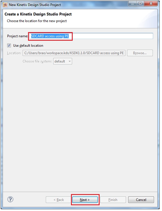
Next select the device: you have 2 options for selecting it, one is by “Boards” and other is by “Processors” i am selecting it from the “Boards” option.

Select the board part number FRDM-K64 and proceed further
Make the selection of processor expert in standalone as shown below:
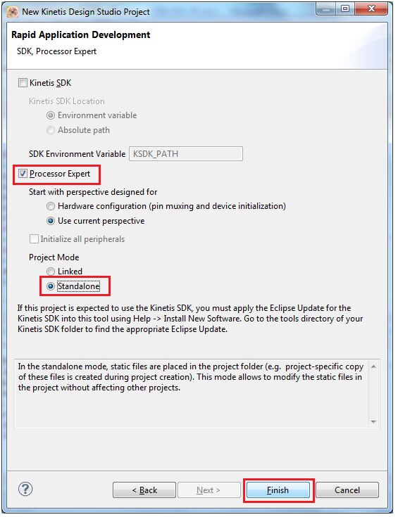
Click finish.
Now click on Processor component

And make the clock configuration as shown below:
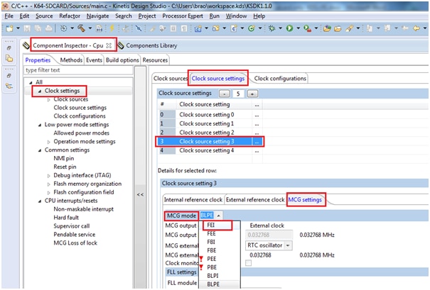
Next change the clock configuration-3 as shown below

Now we will proceed further by adding our components:
Select component library and select FAT_FileSystem

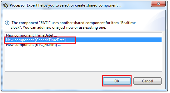
It will ask for you to add the shared components as shown,

Next select “Real time clock” as shown
Now it will create corresponding components in our components window
Now you can see the different shared components created for FAT_FileSystem
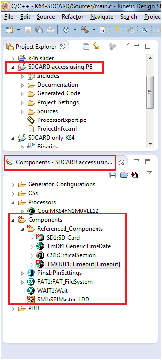
We need to make the corresponding settings for these components as you can see a red cross on it which indicates it has error in settings.
We will go for SD_Card settings
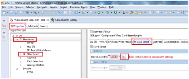
By clicking on slave select pin it prompts for LDDSS where you need to assign hardware pin PTE-4 as shown:

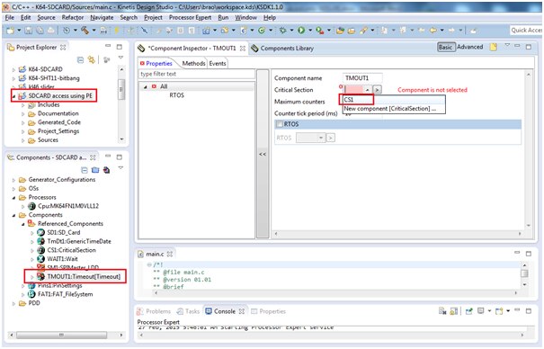
Next coming to TimeOut component, click on it.
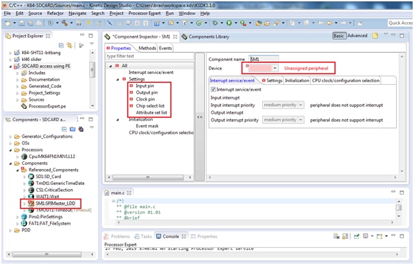
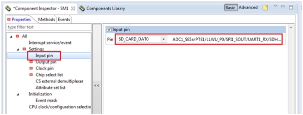
Now coming to next component, i.e SPI Master
SD-card is connected through SPI interface so we need to assign the spi block and its corresponding pins for it.
Here the K64 board is connected to SD card slot via SPI-1
Select the input pin connect to PTE-1 as shown
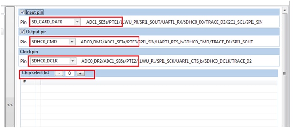
Next output pin connect to PTE-3 as shown

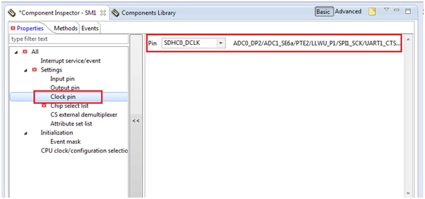
Next clock pin connect to PTE-2
And there is no chip select used hence make it zero by clicking on “-“ button
Now the SPI interface looks as below:
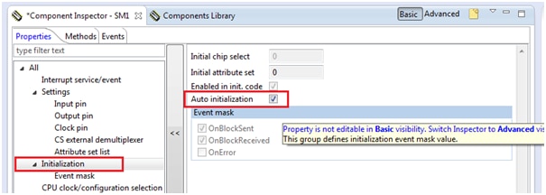
And make the auto initialization radio button to on by clicking the check box.
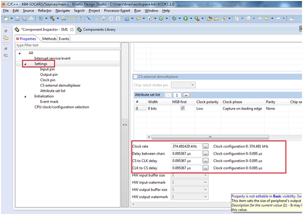
Now need to select the clock rate speed required for SPI interface.
Make the settings as show below:
Now we need to add the component ‘Utility’ this is required for commonly used utility methods, especially safe string copy/concatenation routines.
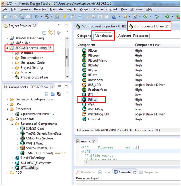
Next add the ConsoleIO component module from component library as shown below:

Double click on the module component to add to our project:
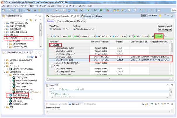
Next select UART0 window from pin configuration main menu as shown below:
As UART0’s RX is connected to PTB16 and UART’s TX is connected to PTB17.
This UART port pins are required for console terminal output.
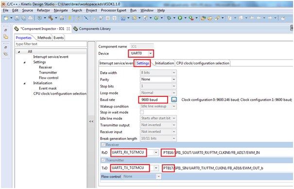
Next click on ConsoleIO_Serial_LDD button as shown below:

We have configured UART0 as shown below:
Now generate the project by clicking the below shown button

It Builds with no errors as shown below:

Now we are going to add our code in “main.c” file
PORT_PDD_SetPinPullSelect(PORTE_BASE_PTR, 6, PORT_PDD_PULL_DOWN);
PORT_PDD_SetPinPullEnable(PORTE_BASE_PTR, 6, PORT_PDD_PULL_ENABLE);
if (FAT1_Init()!=ERR_OK) { /* initialize FAT driver */
ERR_IDLE;
}
if (FAT1_mount(0, &fileSystemObject) != FR_OK) { /* mount file system */
ERR_IDLE;
}
if (FAT1_open(&fp, "./Test_K64.txt", FA_OPEN_ALWAYS|FA_WRITE)!=FR_OK) {
ERR_IDLE;
}
// move to the end of the file
if (FAT1_lseek(&fp, fp.fsize) != FR_OK || fp.fptr != fp.fsize) {
ERR_IDLE;
}
for(cnt=0;cnt<=10;cnt++) {
printf("x y z values are X: %d Y: %d Z: %d\n", x,y,z);
UTIL1_strcat(write_buf, sizeof(write_buf), (unsigned char*)"\r\n");
UTIL1_strcat(write_buf, sizeof(write_buf), (unsigned char*)"Bheema \t ");
UTIL1_strcatNum16s(write_buf, sizeof(write_buf), x);
UTIL1_chcat(write_buf, sizeof(write_buf), '\t');
UTIL1_strcatNum16s(write_buf, sizeof(write_buf), y);
UTIL1_chcat(write_buf, sizeof(write_buf), '\t');
UTIL1_strcatNum16s(write_buf, sizeof(write_buf), z);
UTIL1_strcat(write_buf, sizeof(write_buf), (unsigned char*)"\r\n");
if (FAT1_write(&fp, write_buf, UTIL1_strlen((char*)write_buf), &bw)!=FR_OK) {
ERR_IDLE;
}
}
/* closing file */
(void)FAT1_close(&fp);
FAT1_Deinit();
Now it’s time to build the project, click on the hammer button as shown

You can see the build is finished successfully with no errors
Now it is ready to debug/execute
Click on Debug configuration as shown below:
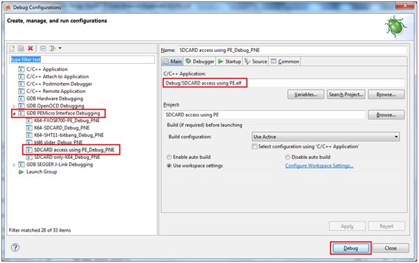
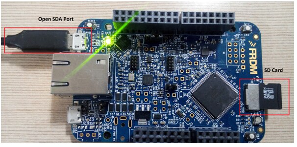
Now connect the K64 board to OPEN SDA port to your computer through USB cable, Then click on Debug button. And insert a SD-Card in the slot as shown below
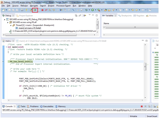
You can see below Debug window screen
Make sure you have open the corresponding hyperterminal window from your ‘Computer Management’ Device manager window:
In my case it is connected to COM23 port

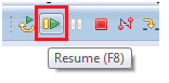
Now click on green ‘Resume’ button
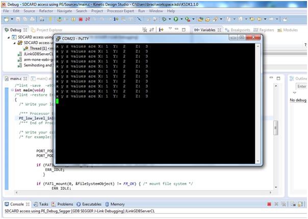
Open COM23 port from any of the hyper terminal application (putty in my case)

The output seen in the terminal is as shown below:
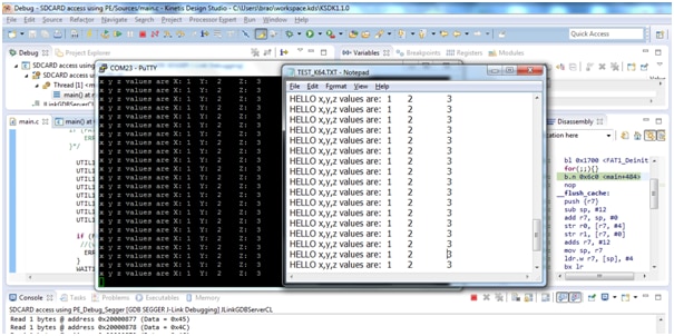
The output seen in the sd-card
Remove the sdcard from K64 and access it through card reader and explore the contents, it will show the new file created “TEST_K64.TXT” as shown below:

The content of this file is as shown below:
I have enclosed the project folder and srec file for quick overview and you can directly test the program by programming the SREC file
Happy SDCard exploring 