


The Cora Z7 is a great development board for experienced developers and those who want to get started with FPGA’s. What makes the Cora Z7 ideal for this is that fact that is it a class of FPGA more correctly called a heterogeneous SoC, as the device combines a traditional FPGA with ARM processors. These two sections of the device are known as the programmable logic and the processing system respectively.
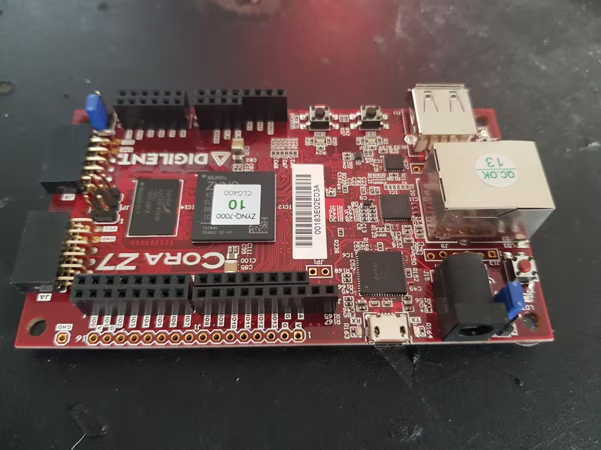
Cora Z7 board on the lab bench
This fusion of FPGA and Processor cores also means engineers who are perhaps more experienced with developing processor-based systems can also quickly and easily develop solutions using the ARM cores and Xilinx IP Library while they develop their Hardware Description Language Skills.
When it comes to the Cora board itself we get a range of popular interfaces such as Pmod and ChipKit / Shield connectors. These allow us to quickly and easily create solutions and we can use both the processors and the programmable logic to connect to them.
So, let’s look at how we can our first Cora Z7 design up and running quickly. Of course, the approach we are about to follow will be identical for any Zynq design.
The first thing we need to do is down download Vivado HLx to work with the CoraZ7 board and most other Zynq development boards the web pack version is sufficient. This comes with everything we need to develop both the programmable logic and the software we wish to run on the Zynq Processor core.
Once we have Vivado downloaded and installed the next stage is ensure Vivado is aware of the board we wish to develop with. This ensures Vivado is aware of the critical things such as the processor DDR configuration and the IO connections to the board. For Digilent boards we can down load the definitions from their Github. Once these files have been downloaded, they need to be installed in Vivado. Doing this is quick and simple copy the board definition files under the following path and restart Vivado
<Vivado Installation Path> data\boards\board_files
Once this is completed we can create our hardware description of the Zynq on the Cora Z7. In the Vivado design we create both the programmable logic contents and the configuration of the Zynq processors within the processing system.
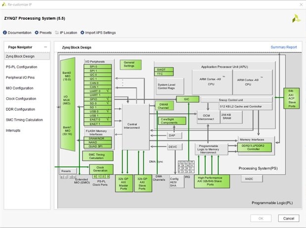
Configuring the Zynq PS in Vivado
The first thing to do is create a project targeting the Cora Z7 board we just installed. Creating a project takes several steps via a project creation dialog.
With Vivado open the first step is to select ->project->new
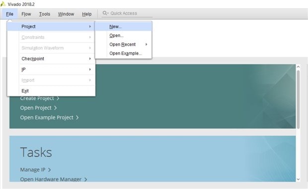
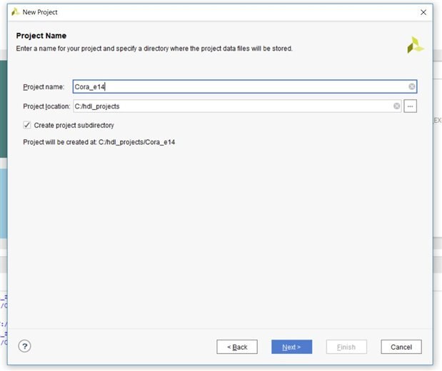
This will open a project creation dialog which can be stepped through to configure the project as we desire. The first step is to define the project name and the location it is stored.
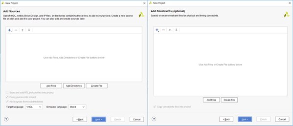
The next thee steps define the project type, which should be RTL project and allow you to add in any pre-existing RTL or constraints.
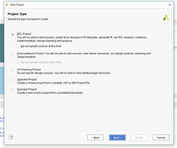
For this example, as we are starting from scratch we will not be adding any RTL or Constraints files.
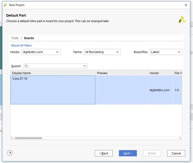
The next stage of the project creation is to select the Cora Z7 development board from the list of boards Vivado is aware of.
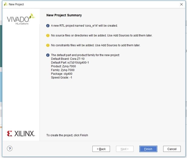
Once the board has been selected this takes us to a project review page, clicking finish will create the project.
Developing solutions for the Zynq can be done visually using the IP integrator (IPI), this enables us to easily connect IP cores provided in the Vivado IP library. Of course, you can also package and add your own RTL cores to the design if you so desire as well.
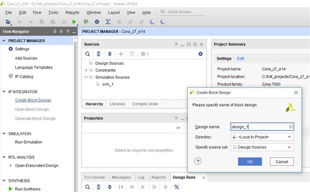
To use IPI first need to create a block diagram to which we can add the IP we require, we do this by clicking on Create Block Design option beneath the IP integrator under Project Manager. This will open a Dialog asking about the block diagrams name and location. For this example leave them as the default and click OK.
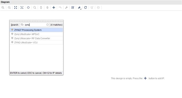
This will create a blank template to which we can add IP from the Vivado IP Catalogue. To add IP we click on the on the add IP button on the menu, from the pop up dialog which appears the first thing we need to add in the Zynq processing system. In the search bar type Zynq and then add in the Zynq7 Processing System.
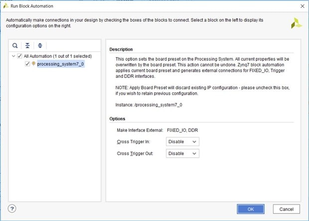
This will add in the Zynq processing system however, it will not be aware of the specific configuration needed for our Cora Z7 board. To configure the processing system for the Cora Z7 we must first run the block automation. Clicking on this will open a dialog, we do not need to make any changes for this application so click OK.
Once this has been completed we are ready to add in the rest of the design. For this design to demonstrate how to add in elements to the programmable logic and access them from the processing system. We are going to add in a BRAM controller and a BRAM which we can read or write from. This will demonstrate the techniques without the need for specific external modules or test equipment.
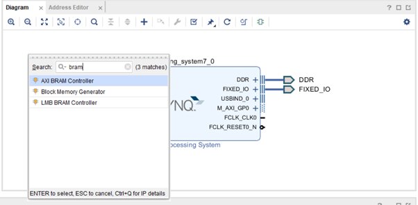
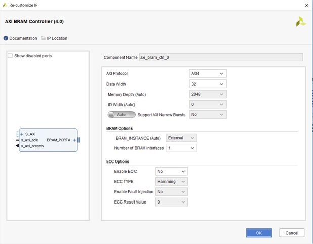
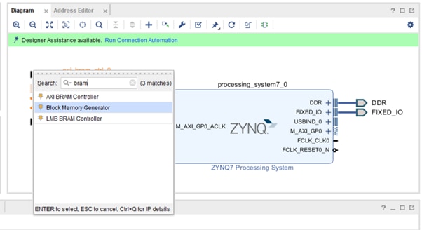
To add in the BRAM controller, click on the ADD IP button again, type BRAM in the search bar and select the AXI BRAM Controller.
Once the BRAM controller is added double clicking allows us to customise this controller. For this application we want to change the number of BRAM interfaces from two to one.
The final element of the design to add is the BRAM itself, again we do this using the ADD IP button.
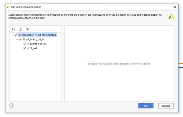
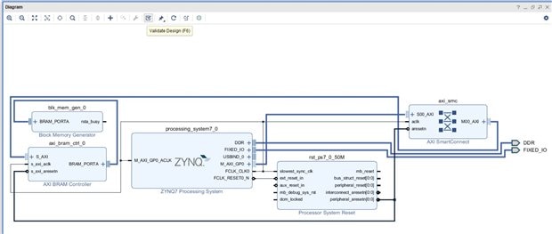
Once both the BRAM and the BRAM Controller are present in the design, we need to connect them to the Zynq Processing system. We could do this by hand and insert the necessary reset and AXI interconnect structures. Alternatively, as we will do in this example leverage the connection automation wizard. Selecting this will open a dialog box, check the BRAM_PORTA and S_AXI on the left-hand side and click OK.
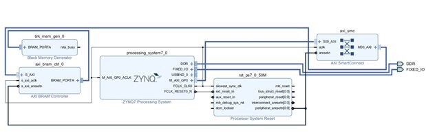
This will map in the AXI BRAM Controller and the BRAM into the Zynq memory space using the M_AXI_GP interface from the PS to the PL. The connection automation will also add in the necessary reset structure as well as connecting the clocks.
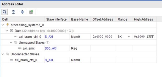
To see the processor system address range the BRAM has been mapped into, click on the address editor tab next to the Diagram tab. This will show you the address range and the memory size allocated.
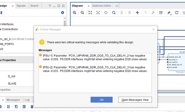
Moving back to the block diagram the next step is to validate the design to ensure there are no issues with the design.
The first time validation is run, you may see a warning about the DDR timings, it is OK to work with the warning as such click OK.
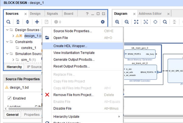
With the block diagram create we need to convert the block diagram into the RTL files which can be synthesised and implemented to provide a bit stream.
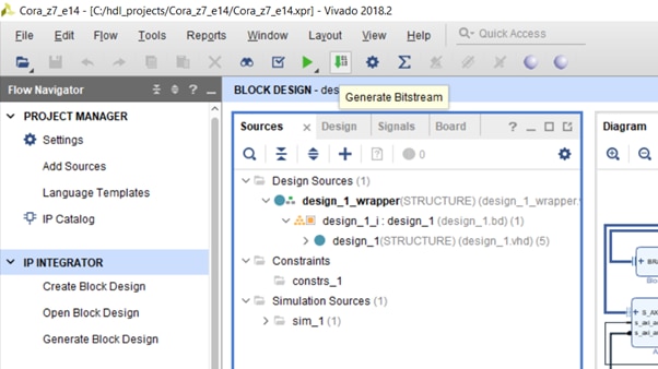
Under the source tab select the bock diagram, right click and choose the option Create HDL Wrapper. This will create a HDL description of the top level of the design, whether this is VHDL or Verilog will depending upon your project language settings.
Selecting this option will generate a pop up, for now we can let Vivado manage this file. It will be re generated as we change the block diagram.

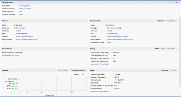
Once this is completed the next step is to generate the BIT file, clicking on the Generate Bitstream button will start the process. The first stage of this process will be to, synthesise each of the IP block used in the design before Synthesising the top level. Depending upon the power of your machine this may take some time.
Once the bit stream is completed, we can review the warnings and the device utilisation by looking at the project summary.
We are now in a position that we can begin to create our software application and test it on the board.
I will explain that in my next blog very soon.

