


General purpose input output (GPIO) is same thing you find in any microcontroller like 8051, avr etc.
Lpc2148 have two General Purpose I/O ports port 0 & port1.port0 & port1 both are 32-bit bi-directional ports like 8051 has four 8-bit bi-directional ports.
In port0,
P0.24, P0.26, P0.27 are not physically available means you can’t find them on chip but still you can write values to them. & P0.31 is available for digital output only.
Also this port has many alternate functions like 8051.
In port1,
P1.0 to P1.15 is not available physically. Only P1.16 to P1.31 is available.
So out of 64 pins 45 pins are covered by port0 & port1.
How to program ports?
Now let’s understand how to program these ports. There are 4 resisters you need to understand to access these ports
IOPIN | For port0 use IOPIN0 & for port1 use IOPIN1.you can also write IO0PIN & IO1PIN both things are same.
Function: GPIO Port Pin value registers. The current state of the GPIO configured port pins can always be read from this register, regardless of pin direction. |
IOSET | For port0 use IOSET0 & for port1 use IOSET1.again you can also write IO0SET & IO1SET both things are same.
Function: GPIO Port Output Set registers. This register controls the state of output pins in conjunction with the IOCLR register. Writing ones produces highs at the corresponding port pins. Writing zeroes has no effect. |
IODIR | For port0 use IODIR0 & for port1 use IODIR1.again you can also write IO0DIR & IO1DIR both things are same.
Function: GPIO Port Direction control register. This register individually controls the direction of each port pin. |
IOCLR | For port0 use IOCLR0 & for port1 use IOCLR1.again you can also write IO0CLR & IO1CLR both things are same.
Function: GPIO Port Output Clear registers. This Register controls the state of output pins. Writing ones produces lows at the corresponding port pins and clears the Corresponding bits in the IOSET register. Writing zeroes has no effect. |
Let’s understand some C program:
We will understand GPIO & register using some C program. First of all remember that header file for lpc2148 is“lpc214x.h” like reg51.h for 8051.
1) Blinking LED using IODIR, IOCLR, and IOSET:
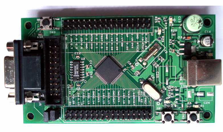
My development board has an LED at P0.21 so we are going to use this LED for our example you can also run this program in Kiel debugger.
Program:
#include<lpc214x.h> void wait(void) //generate small delay {int d; for(d=0;d<1000000;d++); }
int main(void) { IODIR0=0x00200000; //set P0.21 as output port while(1) { IOSET0=0x00200000; //set p0.21 wait(); IOCLR0=0x00200000; //clr p0.21 wait(); }} |
Explanation:
In this program first we select we select which pin will be output & which pin will be input by usingIODIR0.remember 0=input,1=output.
Then we write 1(high) to that pin using IOSET0 register. Remember writing 0 to any bit of IOSET0 have no effect on port pin but writing 1 will produce high on corresponding port pin.
Then we write 0(low) to that pin using IOCLR0 register. Remember writing 0 to any bit of IOCLR0 have no effect on port pin but writing 1 will produce low on corresponding port pin.
Ok, here we complete our first program I know there may be lots of questions in your mind like why can’t we doP0=0x00200000,P0=0x00000000 as we do in 8051 and why we write entire word(32-bit data=word) why we can’t dosbit mybit P0^21 as we do in 8051.
So fact is that both of these things don’t work on ARM but there are ways to do something like that. Let’s see how to do this.
2) How to do sbit mybit P0^21 i.e. address a single bit rather addressing entire register.
First of all keep in mind that there is no keyword like “sbit” in ARM c programming. But we can do this by using“<<” operator. This operator shifts the value on its left side to left by 1 bit by the value specified on its right side.
So now suppose we want to produce 0x00200000 you can just write (0<<21) both will be same.
Program:
#include<lpc214x.h> void wait(void) //generate small delay {int d; for(d=0;d<1000000;d++); }
int main(void) { IODIR0=(1<<21); //set P0.21 as output port while(1) { IOSET0=(1<<21); //set p0.21 wait(); IOCLR0=(1<<21); //clr p0.21 wait(); } } |
3) how to do P0=0x00200000,P0=0x00000000.
Well there is register like P0 in ARM. But there is a register called IOPIN0 which do very much closer task as P0.what ever value you write to IOPIN register will directly appear on physical pins. & you can also read IOPIN register to know the status on pins.
Program:
#include <LPC214X.H> void wait() { int d; for(d=0;d<1000000;d++); }
int main() { IODIR0=0x00200000; while(1) { IOPIN0 =0x00200000; wait(); IOPIN0 =0x00000000; wait(); }} |
4) Let’s we have some input also
Till now we have only output but let’s include some input also. My development board has a button on P0.15 so make a program in which LED will we on when there is high on P0.15 and when there is low on P0.15 LED will be off.
Program:
#include<lpc214x.h> int main() { IODIR0=(1<<21); IODIR0&=~(1<<15); while(1) { if(!(IOPIN0&(1<<15))) { IOCLR0=(1<<21); } if(IOPIN0&(1<<15)) { IOSET0=(1<<21); } } } |