


As an engineer, I am constantly learning new technologies. Hardly a day goes by where I haven’t learned some new technology or aspect of a technology. In the early 70s when cutting my teeth on electronics, integrated solid state electronics was just beginning to make major practical technological advancements. Back then electrons flowed and now the holes flow.
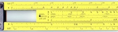
In the early 70s we didn’t have computers, we used slide rules and drafting boards. Wikipedia has an excellent reference on slide rules http://en.wikipedia.org/wiki/Slide_rule. Many engineers that had slide rules then still have them today, including myself. With a little practice you can do multiplication and division quicker on a slide rule than be using a computer or calculator. Using a slide rule required keeping track of exponents in your head as you worked and to this day I am very quick at tracking exponents as a result.
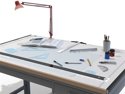
A drafting board consisted of an inclined table with a T-Square or Parallel Bar or both as depicted in this image along with a number of other drawing instruments. Although drafting boards are still used mostly by artists they have been replaced in the electronics industry by computer aided design (CAD) and computer aided engineering (CAE) tools.
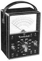
For various reasons my education was very pragmatic. In my freshman year, I built a Heathkit VOM (Volt Ohm Meter) and used it throughout my time in there. I had also built a 5 transistor radio kit. Again, another great article in Wikipedia http://en.wikipedia.org/wiki/Heathkit covers the Heathkit story. If you were really proficient with a good VOM you could tell from the needle response if a capacitor, diode or inductor was in the circuit when using the meter as an Ohmmeter. A capacitor slowed down the needle response while a diode had lower resistance in one direction than the other. An inductor would cause the needle to jump around as you touched and released the probes to the circuit.
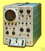
My senior class project was a stereo amplifier built with discrete components. It was actually built on a piece of breadboard with nails for the solder junction. Nearby industry had donated salvaged components to the school and we had an arsenal of manufacturers data books to figure out which of the available parts could be substituted for the parts specified in the reference text as we didn't have a budget for purchasing components. Although very time consuming, this was a practical problem. A whole book can be devoted to the subject of selecting components for a new design. Once we figured out which parts we were going to use, a curve tracer was used to verify the salvaged parts actually worked before putting them into the breadboard. It was fascinating to realize that two of the same kind of parts would vary so much. If you really want to see how a diode or transistor behaves, try connecting a few of them to a curve tracer! At this point finding and eliminating risks in a design was best done by bread boarding critical parts of the design.
Here are some examples of different breadboarding techniques found on a google search
Wire Wrap A hand or electric tool wrapped wire around square posts. Rapid prototypes and eliminated soldering. | 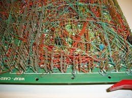 |
Point to point wiring Prefabbed circuit boards with plated through holes on 1/10th inch grid. Some boards had IC patterns laid out on the board to make it easier to locate the chips | 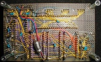 |
Solderless A plastic block with socket strips placed on a 1/10th inch grid enabled rapid prototypes without solder. The board was reusable making it a low cost alternative |  |
Hand Cut Very time consuming to cut the copper using an Exacto knife or a Dremel rotorary tool but works well with sensitive analog and RF circuits. | 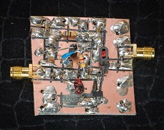 |
Copper Foil The copper foil tape could be used to control impedance when a very rapid prototype was required. | 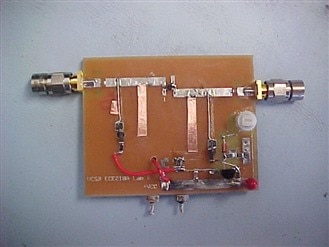 |
When personal computers became mainstream in the electronics industry in the late 80s engineering students started using simulators because they were more cost effective and quicker than purchasing and building kits. Early schematic capture programs such as OrCAD sold for $495 and could integrate with PSpice for simulation. The first version of OrCAD could put the application, related libraries and the schematic on a single 1.2M Byte floppy disk making the design easily portable. Several other powerful but inexpensive Schematic Capture and PCB design tools followed and hobbyists could afford to purchase and use the tools. With computer design and digital files the cost of fabricating a PCB became sufficiently low to prototype some or all of the design on a PCB and bread boarding now plays a minor role. Critical circuits could be better represented and prototyped by a PCB and in the 90s it was becoming more cost effective to skip the hand wired prototype techniques of the previous decades.
Today, engineering students can get a great deal of practical, hands on experience using the various inexpensive (starting under $100) development kits available such as Raspberry Pi, Beagle Board, and Arduino. Manufacturers also offer inexpensive development kits for the various microprocessors, analog chips, regulators and so on. These development kits offer a rapid way to evaluate a circuit and provide a reference design with which to base PCB layout.
In addition there is the internet where you can rapidly find reference materials. In earlier years, when starting a design, you needed a reference library. My favorites were National Semiconductor and TI who used to have the best data books with great application notes. If you didn’t have the right data book you had to have an extensive library of trade magazines such as EDN or EE and start looking through the ads and articles in the hopes you would find a chip or technology that would suit your needs. Weeks could be spent just to find some data on key components. The data books came third class mail and would take over a week to arrive, if they were in stock. Now it can be just a few minutes to do a web search and find several possible solutions for your design. The manufacturer’s data sheets are available directly or through their distributors and you can find out if the part is in stock and buy it all within a matter of minutes.
