


If you're using 10x passive probes with your oscilloscope, it's important to understand the bandwidth of your probing system and how it's affected by various methods of probing the signal of interest. There's a relatively easy way to determine this parameter by probing a fast-edge, 10-MHz signal from a square-wave generator. Doing so can also instruct us in the effects of tip inductance on the probe's bandwidth.
When you look at the frequency spectrum of that fast-edge signal, you'll find that it's a comb spectrum with many frequency components for the multiples of the 10-MHz fundamental.
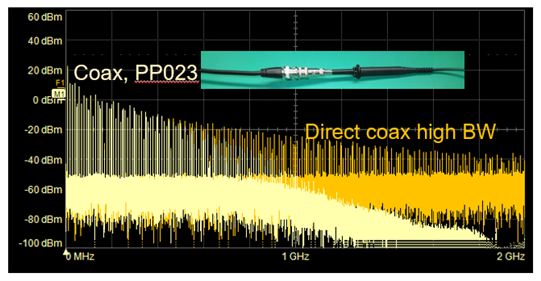
Figure 1: Shown are FFT plots of a 10-MHz, fast-edge square wave reaching the oscilloscope via direct coax connection (orange-yellow plot) and 10x passive probe fitted with a coax tip adapter (straw-colored plot)
First, we connect an oscilloscope to this signal source using a high-bandwidth, direct coaxial connection. We measured the spectral response into the oscilloscope with an FFT math function, and that capture is shown as the orange-yellow trace in Figure 1. The idea here is to create the absolute best-possible scenario in terms of bandwidth for a spectral plot. We can see that the frequency components drop off at 1/f. Consider this our reference plot showing the spectral response of the source and the high-bandwidth interconnect from the source to the oscilloscope itself.
Next, we connected the source to the oscilloscope through the 10x probe using a coaxial tip adapter. This represents the best scenario for measuring the 10x probe bandwidth, and it's the straw-colored plot in Figure 1. At frequencies up to about 500 MHz, the frequency response of both plots is more or less identical. But above 500 MHz, we start to see the "knee" in the coax-to-10x-probe plot, the -3 dB point, where the coax-to-10x-probe plot drops off faster than the direct-coax plot. The 10x probe in this case, Teledyne LeCroy's PP023, is specified with a 500-MHz best case bandwidth, so this measurement bears that out.
What happens when we don't use an absolute best-case, direct coax connection of our source to the oscilloscope, or even a next-best-case scenario of the coaxial tip adapter on the 10x probe? What if we use the probe in the way it's most often used, with a mini-grabber tip and the typical 3-inch ground lead?
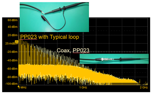
Figure 2: Here, we compare the frequency responses of a coax-to-probe connection to our source to a connection using the probe with mini-grabber tip and ground lead
Figure 2 now uses our coax-to-probe connection as the reference plot, shown again as the straw-colored plot. The orange-yellow plot is the frequency response we get when connecting to the signal source with mini-grabber tip on the 10x probe. Now, instead of the two plots deviating significantly out at 500 MHz, we see the drop off at a much lower frequency of around 200 MHz. What we're seeing here is the impact on bandwidth of that longer return path with its greater inductance discontinuity.
Another reason for avoiding that loop inductance in the tip is that the frequency response isn't flat any longer and we introduce peaking artifacts into our signal. We can see this clearly by looking at the signal in the time domain.
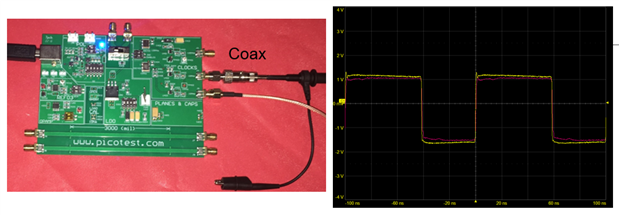
Figure 3: Here, we look at the source in the time domain captured with direct coax connection (yellow trace) and with a coax-to-probe connection (red trace). (Board courtesy of Steve Sandler)
The yellow trace in Figure 3 (acquired on Teledyne LeCroy's WavePro 804HD, with 8 GHz analog bandwidth) is our 10-MHz fast-edge square wave fed into the oscilloscope with the high-bandwidth, direct coaxial connection of Figure 1. The red trace is the same signal using the coax-to-probe connection method; the scales of the two traces are the same because of the 1-MΩ input impedance for the probe. The two traces match up quite closely, which speaks well of the probe's frequency response.
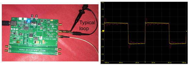
Figure 4: This pair of traces compares an acquisition made a direct coax connection (yellow trace) with one made using a mini-grabber tip and long ground lead (red trace)
In Figure 4, we replace the coax-to-probe connection with the mini-grabber tip and long ground lead, and the impact of that connection is obvious. Again, we're comparing to the direct-coax-fed trace in yellow, while the mini-grabber/ground lead trace is in red. We find that our signal now displays a substantial amount of peaking and ringing because of the loop inductance of the tip and the probe's high-pass filter capacitance.
All of this serves to illustrate that good probing habits mean minimizing the tip inductance so that we have access to the probe's true maximum bandwidth. If we're looking at relatively low-frequency signals, it's not so critical, but when we want to probe in the 100-MHz range with a 10x passive probe, it is a definite matter of concern.
In an upcoming post, we'll take a look at cable reflections in 10x passive probes and what they mean for measurement accuracy.
Previous posts in this series:
Top Comments
-

DAB
-
Cancel
-
Vote Up
0
Vote Down
-
-
Sign in to reply
-
More
-
Cancel
Comment-

DAB
-
Cancel
-
Vote Up
0
Vote Down
-
-
Sign in to reply
-
More
-
Cancel
Children