


A while back I showed an issue I had on my Keysight U1461AU1461A Insulation Multimeter when carrying out insulation testing on large generator rotors that led to invalid results being displayed on the meter when in fact the winding insulation was perfectly acceptable
Keysight U1461A Insulation Multimeter Test Fault Blog
I have swapped a few emails with Keysight and they requested that I carried out some further tests on the rotor winding with the meter set to read current instead of the resistance value when carrying out an insulation test. This blog will details the findings of those tests.
I hadn't actually realised that you could change the displayed measurement on the instrument. To change to reading current, the instrument is selected to the desired range and before setting up the type of test, the display can be cycled between reading MOhms and uAmps using the range key. If the meter is set to a timed, DAR or PI test, then this display cycle function is disabled. Unlike the MIT420 insulation tester, that I road tested last year, that can cycle between displaying the test time, voltage and current on an auxiliary display during the test, the Keysight unit has to have everything set up prior to starting the test.

Other than selecting to display current, the test on the rotor winding was conducted in exactly the same manner as before with the positive lead of the insulation tester connected to earth and the negative to the winding.
The initial test was carried out at 500V with the Keysight and produced a complete test but it was noted that the insulation resistance reading was down to 494MOhm in comparison to the reading of 1.78GOhm on the previous test. A test was therefore conducted with the MIT420 to verify the insulation value that recorded a comparable reading of 471MOhm.
Further tests were therefore conducted at different voltage levels to determine if there would be any issues with the results, the concept in mind being that if the test voltage is dropped the insulation resistance value could rise and is it this factor that is upsetting the Keysight unit.
The table below shows the results of the various tests conducted.
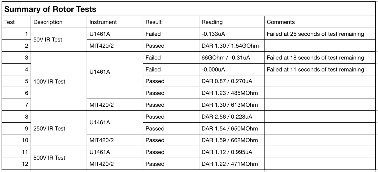
When tested at 250V, the insulation resistance was seen to increase. The display on the Keysight was seen to be more erratic but the unit did work and produced a complete test result. At 100V, the Keysight produced erratic results, some tests completed, but some did not. The Megger unit worked without fault and it can be seen that the insulation resistance value was similar to the 250V test results.
The video below is about 100 seconds long and shows the 100V test with the Keysight and Megger units side by side. You can see the Keysight unit fail and the Megger continue to the end of the test and record a complete set of results. The tests were conducted one after another, I have just merged the videos to run them side by side.
At 50V, the Keysight unit failed to complete any test. The Megger unit produced consistent results and it can be seen that the insulation resistance value has gone up to 1.58GOhm, near to the test results carried out in December 2017, when the Keysight unit failed to complete any of the tests.
It is still unclear what the issue is with the Keysight but these further tests along with the reduced insulation resistance of the rotor have shown that when the resistance is somewhere between 600MOhm and 1GOhm the unit starts to act erratically The current display on the meter will go into reverse polarity as if there is some back EMF from the rotor winding disrupting the reading This behaviour can also be seen on the secondary ammeter used to verify the operation of the U1461AU1461A
This only appears on large windings. I have successfully tested 3-phase induction motors and calibration resistors above 600MOhm and 1GOhm without any issue.
The results are with Keysight, so I will wait to see if there is any more feedback or a conclusion from them.