element14 Community
element14 Community
    Register Log In
  • Site
  • Search
  • Log In Register
  • Members
    Members
    • Achievement Levels
    • Benefits of Membership
    • Feedback and Support
    • Members Area
    • Personal Blogs
    • What's New on element14
  • Learn
    Learn
    • eBooks
    • Learning Center
    • Learning Groups
    • STEM Academy
    • Webinars, Training and Events
  • Technologies
    Technologies
    • 3D Printing
    • Experts & Guidance
    • FPGA
    • Industrial Automation
    • Internet of Things
    • Power & Energy
    • Sensors
    • Technology Groups
  • Challenges & Projects
    Challenges & Projects
    • Arduino Projects
    • Design Challenges
    • element14 presents
    • Project14
    • Project Groups
    • Raspberry Pi Projects
  • Products
    Products
    • Arduino
    • Avnet Boards Community
    • Dev Tools
    • Manufacturers
    • Product Groups
    • Raspberry Pi
    • RoadTests & Reviews
  • Store
    Store
    • Visit Your Store
    • Or choose another store...
      • Europe
      •  Austria (German)
      •  Belgium (Dutch, French)
      •  Bulgaria (Bulgarian)
      •  Czech Republic (Czech)
      •  Denmark (Danish)
      •  Estonia (Estonian)
      •  Finland (Finnish)
      •  France (French)
      •  Germany (German)
      •  Hungary (Hungarian)
      •  Ireland
      •  Israel
      •  Italy (Italian)
      •  Latvia (Latvian)
      •  
      •  Lithuania (Lithuanian)
      •  Netherlands (Dutch)
      •  Norway (Norwegian)
      •  Poland (Polish)
      •  Portugal (Portuguese)
      •  Romania (Romanian)
      •  Russia (Russian)
      •  Slovakia (Slovak)
      •  Slovenia (Slovenian)
      •  Spain (Spanish)
      •  Sweden (Swedish)
      •  Switzerland(German, French)
      •  Turkey (Turkish)
      •  United Kingdom
      • Asia Pacific
      •  Australia
      •  China
      •  Hong Kong
      •  India
      •  Korea (Korean)
      •  Malaysia
      •  New Zealand
      •  Philippines
      •  Singapore
      •  Taiwan
      •  Thailand (Thai)
      • Americas
      •  Brazil (Portuguese)
      •  Canada
      •  Mexico (Spanish)
      •  United States
      Can't find the country/region you're looking for? Visit our export site or find a local distributor.
  • Translate
  • Profile
Personal Blogs
  • Members
  • More
Personal Blogs
Legacy Personal Blogs LM386 Audio Amplifier
  • Blog
  • Documents
  • Mentions
  • Sub-Groups
  • Tags
  • More
  • Cancel
  • New
Blog Post Actions
  • Subscribe by email
  • More
  • Cancel
  • Share
  • Subscribe by email
  • More
  • Cancel
Group Actions
  • Group RSS
  • More
  • Cancel
Engagement
  • Author Author: mrchunckuee
  • Date Created: 13 Feb 2016 4:14 AM Date Created
  • Views 1317 views
  • Likes 4 likes
  • Comments 11 comments
  • audio amplifier
  • lm386
  • lm386 audio amplifier
Related
Recommended

LM386 Audio Amplifier

mrchunckuee
mrchunckuee
13 Feb 2016

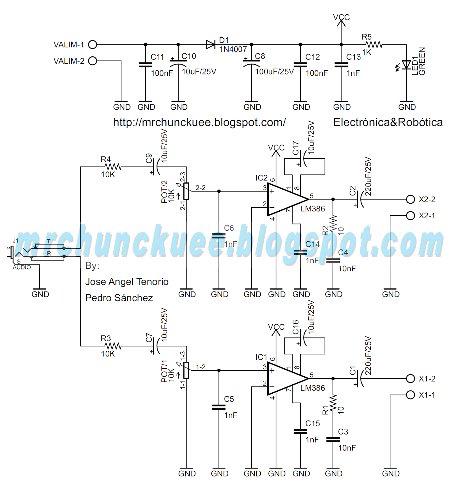
Greetings! My first post on Element, is a small audio amplifier using LM386 integrated.


For the design has been based on the one proposed in the datasheet (Gain = 200), some components and filters are added to the feed inlet (VALIM = 12V), the circuit used is this:

AMPLIFICADOR%2BDE%2BAUDIO%2BCON%2BLM386.png

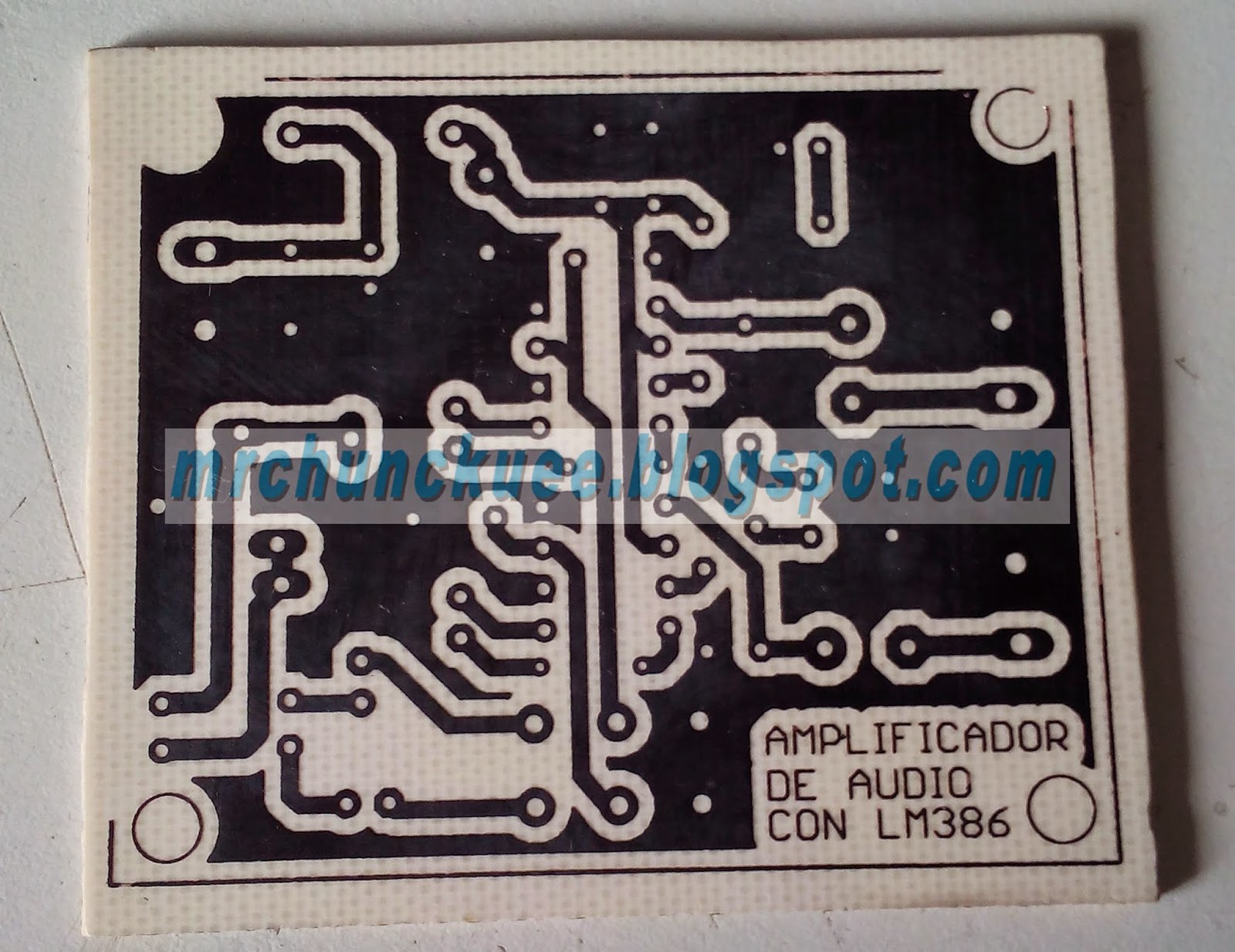
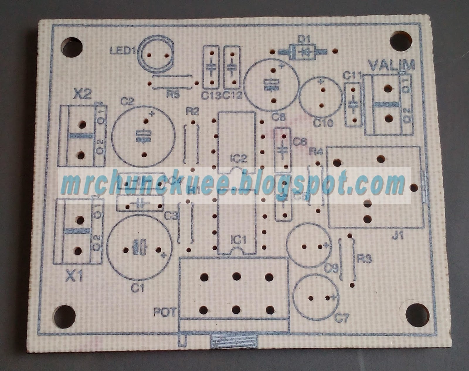
Here more photos of the PCB:

buttom pcb

3%2BAMPLIFICADOR%2BDE%2BAUDIO%2BCON%2BLM386.jpg

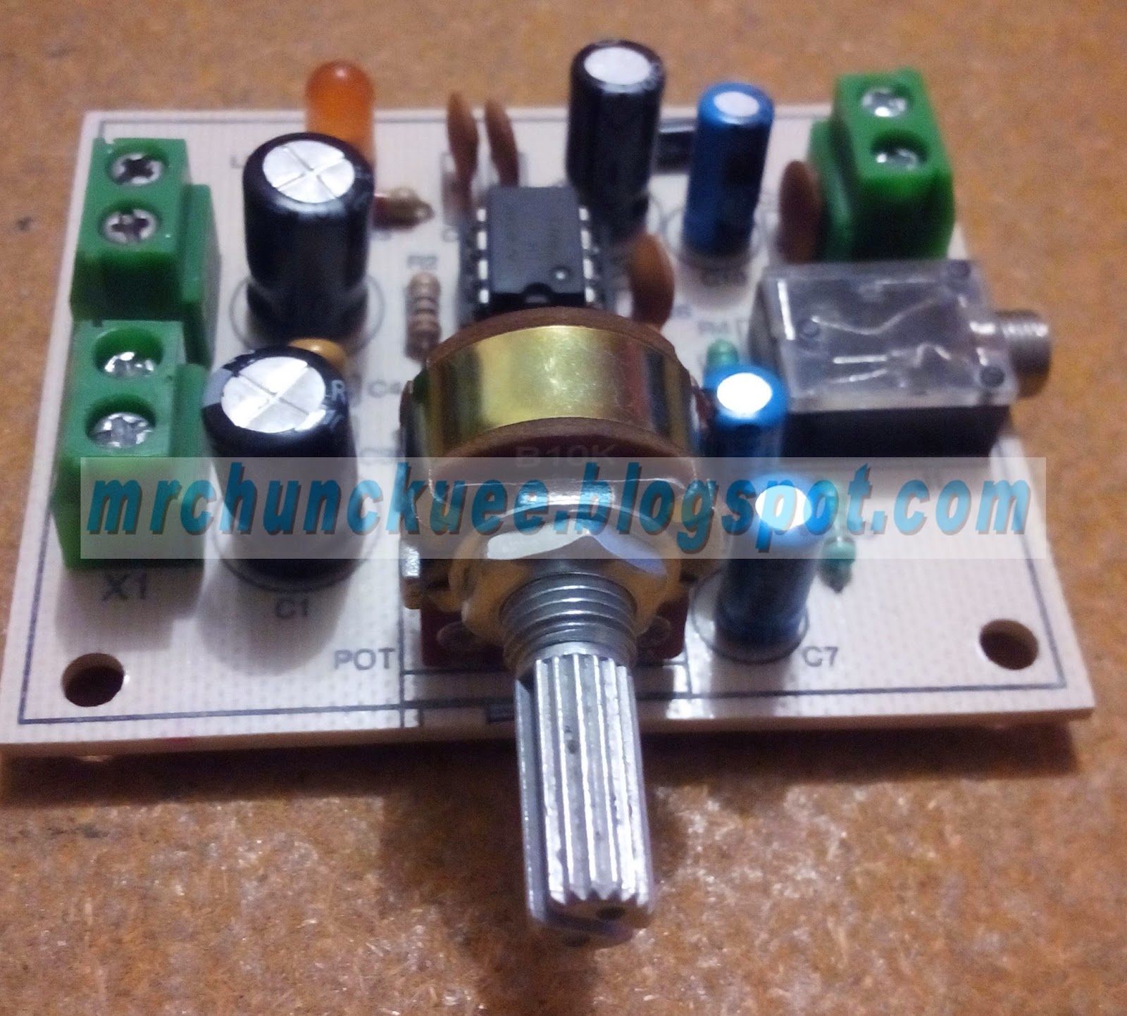
The final PCB with all componences looks like this:

4%2BAMPLIFICADOR%2BDE%2BAUDIO%2BCON%2BLM386.jpg

Here one video of the circuit in action (video in spanish):


You don't have permission to edit metadata of this video.
Edit media
x
image
Upload Preview
image


See more projects or info in my blog (in spanish)

  • Sign in to reply

Top Comments

  • jw0752
    jw0752 over 7 years ago +2
    Hi Pedro, This was a very nice project. It is really good that you are open to learning. I have learned a lot of new things by listening to michaelkellett as he always has good solid advice. John
  • jc2048
    jc2048 over 7 years ago in reply to DAB +2
    Page 4 of the datasheet has a graph of Voltage Gain vs Frequency. That shows about 40kHz for the IC itself with a gain of 200 (C pin1 to pin8 = 10uF). Out of curiousity, I tried simulating the input network…
  • nick123
    nick123 over 7 years ago +1
    Welcome, cool amp, see if you can get a guitar amplified through there
Parents
  • DAB
    DAB over 7 years ago

    What is the bandwidth for the amplifier?


    DAB

    • Cancel
    • Vote Up 0 Vote Down
    • Sign in to reply
    • More
    • Cancel
  • jc2048
    jc2048 over 7 years ago in reply to DAB

    Page 4 of the datasheet has a graph of Voltage Gain vs Frequency. That shows about 40kHz for the IC itself with a gain of 200 (C pin1 to pin8 = 10uF).


    Out of curiousity, I tried simulating the input network (from jack socket to pin3 of the IC) and here's the response with the pot set to 100% and the input resistance of the amplifier as 50k (the typical value from the datasheet).


    image


    Even if the amplifier gain was less than 200 and the bandwidth of the amplifier was therefore higher, the high end -3dB point for the whole circuit would still be around 30kHz because of the action of C6 at the input. I don't know why C6 is there - possibly it is intended to filter out rf from medium wave broadcasts that might be picked up on the input leads and then get rectified by the semiconductors in the IC. Alternatively, it might be intended to reduce the possibility of oscillation at higher frequencies (even with the natural roll-off of the amplifier, the IC still has some gain at 1MHz where the possibility of capacitive coupling from the output to the input increases).


    For the output network, I tried simulating with a 8ohm resistor for the loudspeaker, but you should be a bit (very?) skeptical because I've just assumed the IC output is a perfect voltage source which it obviously isn't and an 8R resistor isn't a very good model for a loudspeaker. It does, however, give some idea as to what is going on and how it's going to behave.


    image


    Not surprisingly, the low end is dominated by the output capacitor and looks like it might be around 100Hz.


    So, overall we could say something like 100Hz-30kHz. That's fine for a small speaker and the kind of applications where you'd use the circuit. [It's only a simple amplifier and the distortion is more than 1% at higher frequencies, so we're not really in the realms of hi-fi here.]

    • Cancel
    • Vote Up +2 Vote Down
    • Sign in to reply
    • More
    • Cancel
Comment
  • jc2048
    jc2048 over 7 years ago in reply to DAB

    Page 4 of the datasheet has a graph of Voltage Gain vs Frequency. That shows about 40kHz for the IC itself with a gain of 200 (C pin1 to pin8 = 10uF).


    Out of curiousity, I tried simulating the input network (from jack socket to pin3 of the IC) and here's the response with the pot set to 100% and the input resistance of the amplifier as 50k (the typical value from the datasheet).


    image


    Even if the amplifier gain was less than 200 and the bandwidth of the amplifier was therefore higher, the high end -3dB point for the whole circuit would still be around 30kHz because of the action of C6 at the input. I don't know why C6 is there - possibly it is intended to filter out rf from medium wave broadcasts that might be picked up on the input leads and then get rectified by the semiconductors in the IC. Alternatively, it might be intended to reduce the possibility of oscillation at higher frequencies (even with the natural roll-off of the amplifier, the IC still has some gain at 1MHz where the possibility of capacitive coupling from the output to the input increases).


    For the output network, I tried simulating with a 8ohm resistor for the loudspeaker, but you should be a bit (very?) skeptical because I've just assumed the IC output is a perfect voltage source which it obviously isn't and an 8R resistor isn't a very good model for a loudspeaker. It does, however, give some idea as to what is going on and how it's going to behave.


    image


    Not surprisingly, the low end is dominated by the output capacitor and looks like it might be around 100Hz.


    So, overall we could say something like 100Hz-30kHz. That's fine for a small speaker and the kind of applications where you'd use the circuit. [It's only a simple amplifier and the distortion is more than 1% at higher frequencies, so we're not really in the realms of hi-fi here.]

    • Cancel
    • Vote Up +2 Vote Down
    • Sign in to reply
    • More
    • Cancel
Children
No Data
element14 Community

element14 is the first online community specifically for engineers. Connect with your peers and get expert answers to your questions.

  • Members
  • Learn
  • Technologies
  • Challenges & Projects
  • Products
  • Store
  • About Us
  • Feedback & Support
  • FAQs
  • Terms of Use
  • Privacy Policy
  • Legal and Copyright Notices
  • Sitemap
  • Cookies

An Avnet Company © 2023 Premier Farnell Limited. All Rights Reserved.

Premier Farnell Ltd, registered in England and Wales (no 00876412), registered office: Farnell House, Forge Lane, Leeds LS12 2NE.

ICP 备案号 10220084.

Follow element14

  • X
  • Facebook
  • linkedin
  • YouTube