


CadSoftusa Eagle PCB design software already has a lot of Farnell Element 14 components in its libraries - and more you can add from here. But what happens if there is something you want to use that isn't there?
Recently I wanted to attach a CR2033 3V battery to a PCB. The battery holder I chose, the Renata Hu2032-LF, did not already have a Eagle device associated with it.
This blog post will explain how I adapted an Eagle library device (LI Battery Varta CR2032H) (below)
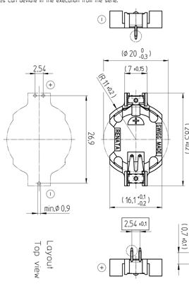
for use with a Renata Hu2032-LF (below)
- Open Eagle
- Make sure all libraries and projects are closed
- Click: File, New, Project (and name project - e.g. Lucy_Library)
- Make sure Project Lucy_Library is open (green dot by it)
- Right click on Lucy_Library, New, Library
- Click back on the Control Panel WITHOUT closing the new library
- Expand folder Libraries (this is on the same level as Projects)
- In Libraries, expand folder battery.lib - but do not open it
- In battery.lib right click on CR2032H, then click on "copy to library"
- You can tell from the directory path in the top line the name of the library it has saved it into.
- Maximise the Lucy_Library window.
- Single click on Description (in blue on left hand side).
- Change the Description it is sort of HTML code just substituting the words you don't want should be fine I changed"Varta to"Renata HU2032-LFHU2032-LF
- At the top of the window are three icons like this:

They are:
Device The device is the combination of the symbol and the package It is named CR2032H.dev
Package The package is the foot print and connections of a real component.
and Symbol The symbol is the symbol you would draw on a schematic.
If you click on the package icon, then select the only one that is there (CR2032H), you will see that it has two green donuts (called vias pads (Thanks Workshopshed for the correction) for the positive pins at the top and one green donut for the negative pin at the bottom (This stops you being able to put the component in the wrong way round - there's a word for it: poka-yoke). The green bit of the via pad is the copper disk on the PCB, the hole in the middle is the hole through the PCB.
The Renata HU2032-LFHU2032-LF has two positive pins and one negative pin, and so the symbol for the Varta battery holder can be used as it is. However, the package needs to be changed.
- Go back to the Device window (click on device icon, select CR2032H)
- Right click the CR2032H under package in the middle.
- Click edit package
- The package will now appear in a window.
- Click on the trash can / delete an object icon
- Then click on all the outline white lines, leaving only the text, the "+" and "-" and the green vias pads.
- Click on the "information" icon and then click on the top left green via pad. The drill sizes and positions need checking / changing.

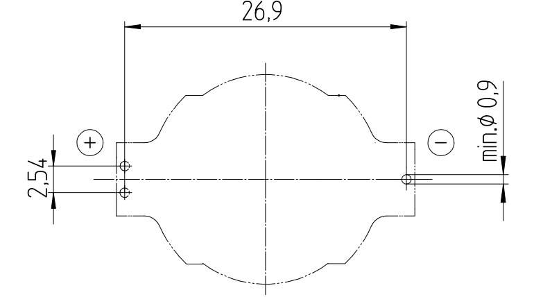
- The data sheet for the Renata HU2032-LFHU2032-LF shows the minimum pin hole diameter to be 0.9mm the"x distance from the centre to the pins to be 13.45mm and the"y distance from the centre line to the positive pins to be 1.27mm
- As shown here:

- The default units on Eagle are inches. However, if dimensions are entered, followed by "mm", it will auto-convert.
- The drill size is 0.4 inches, which is near enough to 1mm - a little bit larger than the minimum of 0.9mm, so leave that as it is.
- The position for the green vias pads needs to be changed.
- Click on "information icon" then the top left via pad, and change the Position to be -0.05 and 0.53 (values given in inches, but you could put in 1.27mm and 13.45mm respectively, as long as you remember to put in the mm.
- Click on "information icon" then the top right via pad, and change the Position to be 0.05 and 0.53 (values given in inches).
- Click on "information icon" then the bottom via pad, and change the Position to be 0 and -0.53 (values given in inches).
- Now we want to draw some white lines. These will appear the silk screen and serve to remind us where the parts go and to not place anything else over them.
- Next draw the circle where the battery will go:
Click the circle icon. Left click to define the circle centre (put this on the cross (not the plus symbol) in the middle of the window). Left click to mark the radius. It doesn't really matter where - we will change it in the next step. - Click on "information icon" then on the circle. Change the width to 0.006 (inches) and the radius to 10mm (remember the mm!)
- Click on the "Draw Lines" icon. Change the width (at the top) to 0.006 (inches).
- Draw a rectangle - we'll change the dimensions in the next step:
Click on "information icon" then on one of the lines. Change the From to: -0.138 (next box along) -0.56 and the To to: -0.138 (next box along) 0.56 click OK.
Click on another line (if you haven't selected another icon, it will remember you are still using the "information icon") Change From to: 0.138 (next box along) -0.56 and the To to: 0.138 (next box along) 0.56 click OK.
Click on another line - change From to: -0.138 (next box along) 0.56 and the To to: 0.138 (next box along) 0.56 click OK.the click OK
Click on another line - change From to: -0.138 (next box along) -0.56 and the To to: 0.138 (next box along) -0.56 click OK.the click OK - Save (save regularly!)
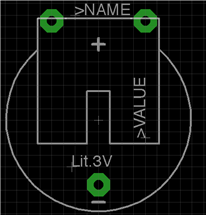
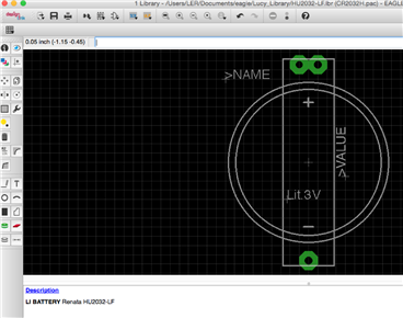
- You should now have something that looks like this:

- Which if you have some imagination looks like the HU2032-LFHU2032-LF layout top view from the data sheet

- Save
- I moved the "name" from inside the layout to outside - so I can see what it is called after I have soldered the component. Do this by using the "Move" command.
- Finally I changed the description at the bottom to"Renata HU2032-LFHU2032-LF

- Save again!
- That's it. You now have an Eagle device for the Farnell Element 14 component you want.
- When you want to add it to your schematic, remember to look in the library directory that you saved (Lucy_Library). If you cannot see your library, you may need to click "use" from the control panel.


If you have any problems, please do leave a comment. I am still relatively new to this and would love to hear any shortcuts or improvements.
Huge thanks to @rocketengines, who has a lot of experience using Eagle and is mentoring me.
Top Comments