element14 Community
element14 Community
    Register Log In
  • Site
  • Search
  • Log In Register
  • Community Hub
    Community Hub
    • What's New on element14
    • Feedback and Support
    • Benefits of Membership
    • Personal Blogs
    • Members Area
    • Achievement Levels
  • Learn
    Learn
    • Ask an Expert
    • eBooks
    • element14 presents
    • Learning Center
    • Tech Spotlight
    • STEM Academy
    • Webinars, Training and Events
    • Learning Groups
  • Technologies
    Technologies
    • 3D Printing
    • FPGA
    • Industrial Automation
    • Internet of Things
    • Power & Energy
    • Sensors
    • Technology Groups
  • Challenges & Projects
    Challenges & Projects
    • Design Challenges
    • element14 presents Projects
    • Project14
    • Arduino Projects
    • Raspberry Pi Projects
    • Project Groups
  • Products
    Products
    • Arduino
    • Avnet & Tria Boards Community
    • Dev Tools
    • Manufacturers
    • Multicomp Pro
    • Product Groups
    • Raspberry Pi
    • RoadTests & Reviews
  • About Us
  • Store
    Store
    • Visit Your Store
    • Choose another store...
      • Europe
      •  Austria (German)
      •  Belgium (Dutch, French)
      •  Bulgaria (Bulgarian)
      •  Czech Republic (Czech)
      •  Denmark (Danish)
      •  Estonia (Estonian)
      •  Finland (Finnish)
      •  France (French)
      •  Germany (German)
      •  Hungary (Hungarian)
      •  Ireland
      •  Israel
      •  Italy (Italian)
      •  Latvia (Latvian)
      •  
      •  Lithuania (Lithuanian)
      •  Netherlands (Dutch)
      •  Norway (Norwegian)
      •  Poland (Polish)
      •  Portugal (Portuguese)
      •  Romania (Romanian)
      •  Russia (Russian)
      •  Slovakia (Slovak)
      •  Slovenia (Slovenian)
      •  Spain (Spanish)
      •  Sweden (Swedish)
      •  Switzerland(German, French)
      •  Turkey (Turkish)
      •  United Kingdom
      • Asia Pacific
      •  Australia
      •  China
      •  Hong Kong
      •  India
      • Japan
      •  Korea (Korean)
      •  Malaysia
      •  New Zealand
      •  Philippines
      •  Singapore
      •  Taiwan
      •  Thailand (Thai)
      • Vietnam
      • Americas
      •  Brazil (Portuguese)
      •  Canada
      •  Mexico (Spanish)
      •  United States
      Can't find the country/region you're looking for? Visit our export site or find a local distributor.
  • Translate
  • Profile
  • Settings
Personal Blogs
  • Community Hub
  • More
Personal Blogs
Legacy Personal Blogs Make Your own FREE Bluetooth Serial Module : PART 2
  • Blog
  • Documents
  • Mentions
  • Sub-Groups
  • Tags
  • More
  • Cancel
  • New
  • Share
  • More
  • Cancel
Group Actions
  • Group RSS
  • More
  • Cancel
Engagement
  • Author Author: gsgill112
  • Date Created: 22 Nov 2014 6:53 PM Date Created
  • Views 809 views
  • Likes 1 like
  • Comments 4 comments
  • bluetooth
  • lmx9838
  • bluetooth2.0
  • bluetooth_module
  • module
Related
Recommended

Make Your own FREE Bluetooth Serial Module : PART 2

gsgill112
gsgill112
22 Nov 2014

Hi,

This is continuation to my previous blog. In this post I will go through the steps of building the module itself and share some of my findings image


NOTE : Unfortunately due to lack of a good camera with stand I haven't recorded the construction Process :(.


So, lets Go image 

In my last post I had mentioned how to procure the IC and basic components you may need for constructing the module. I had also posted some reference images to follow. Hopefully by now you guys may have received the module  image image


Step 1  :  Preparation


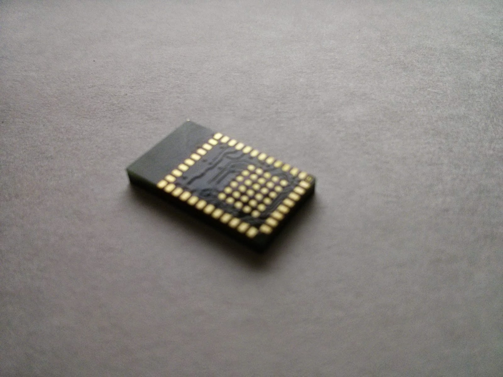
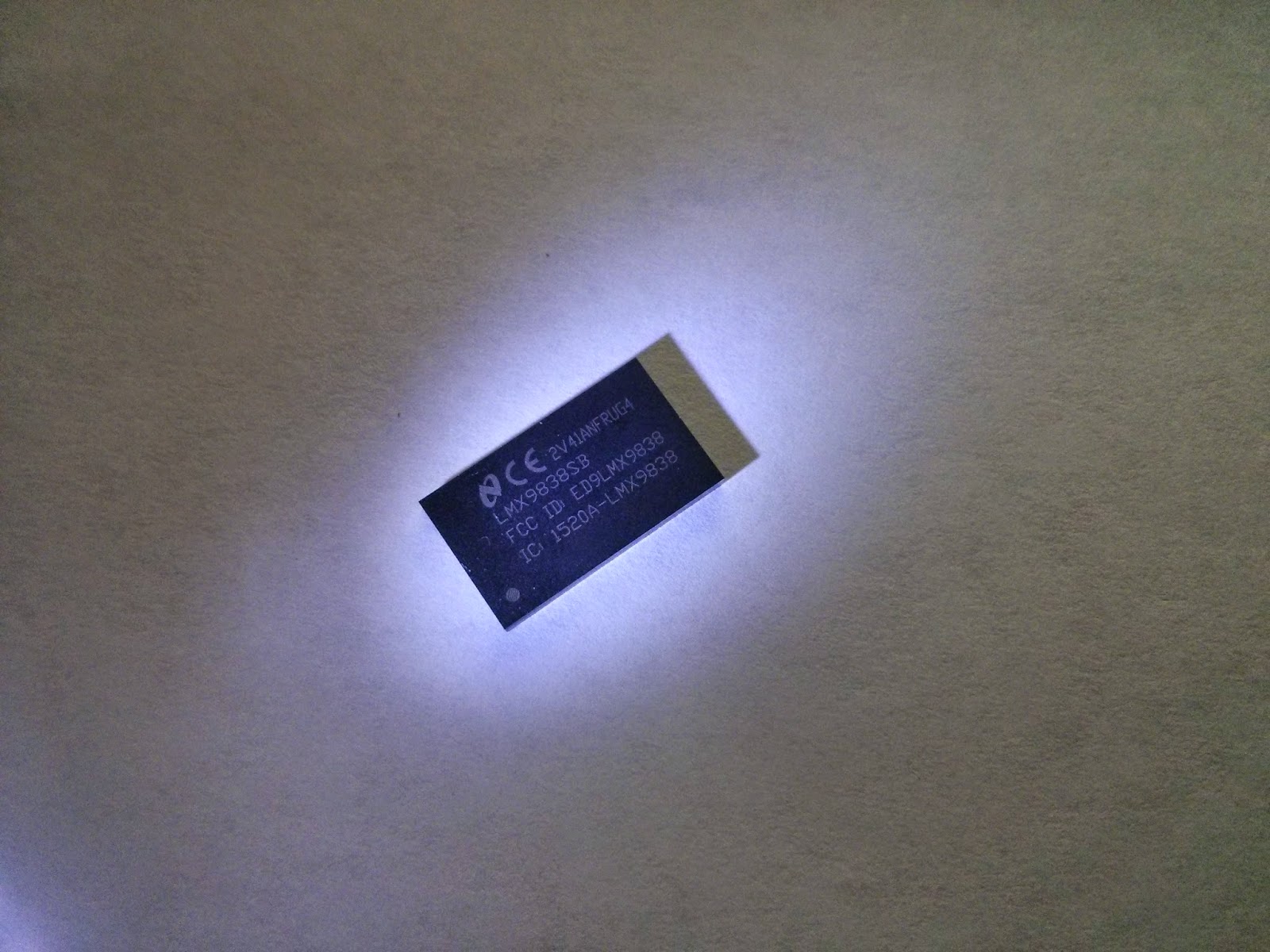
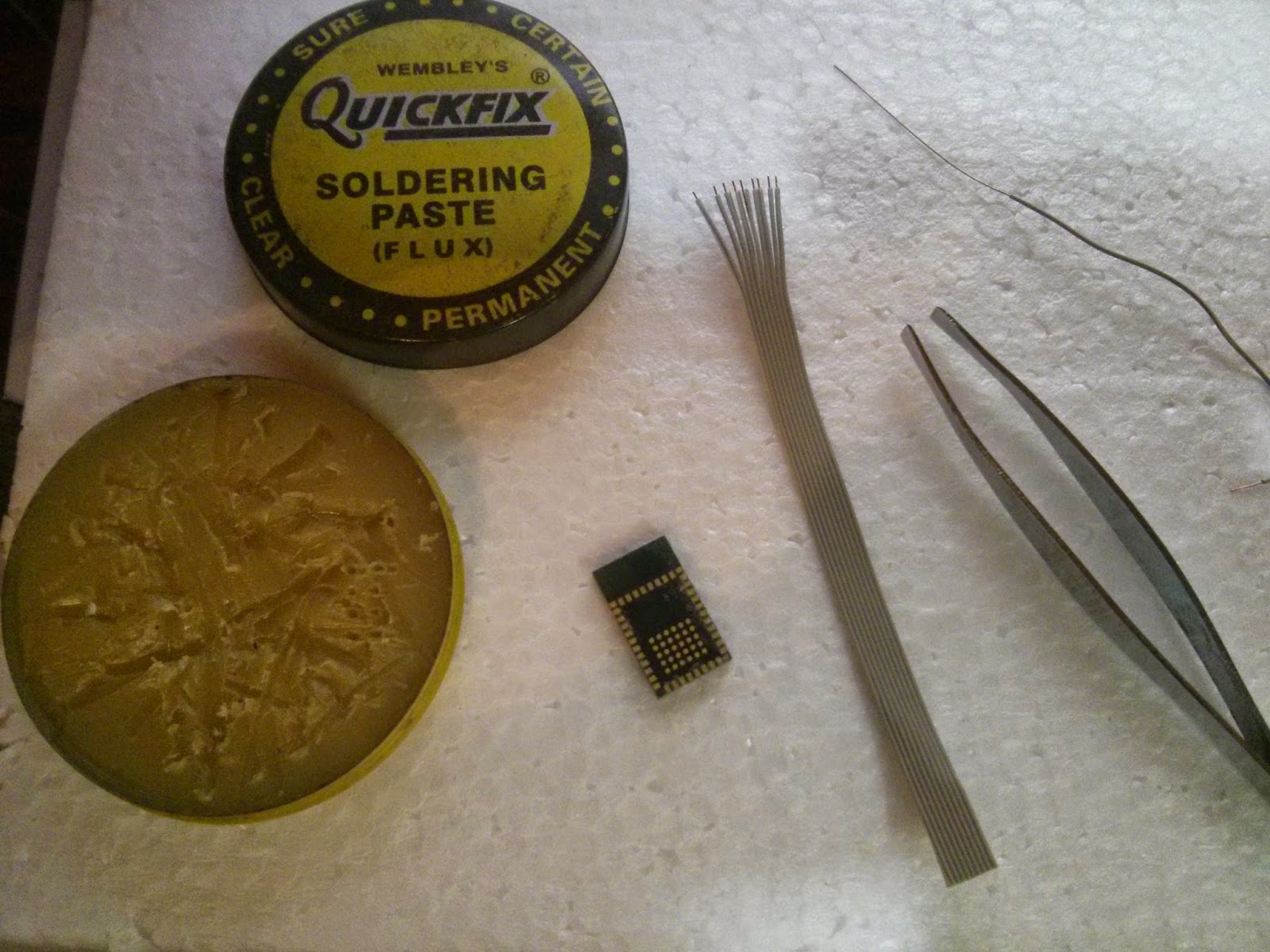
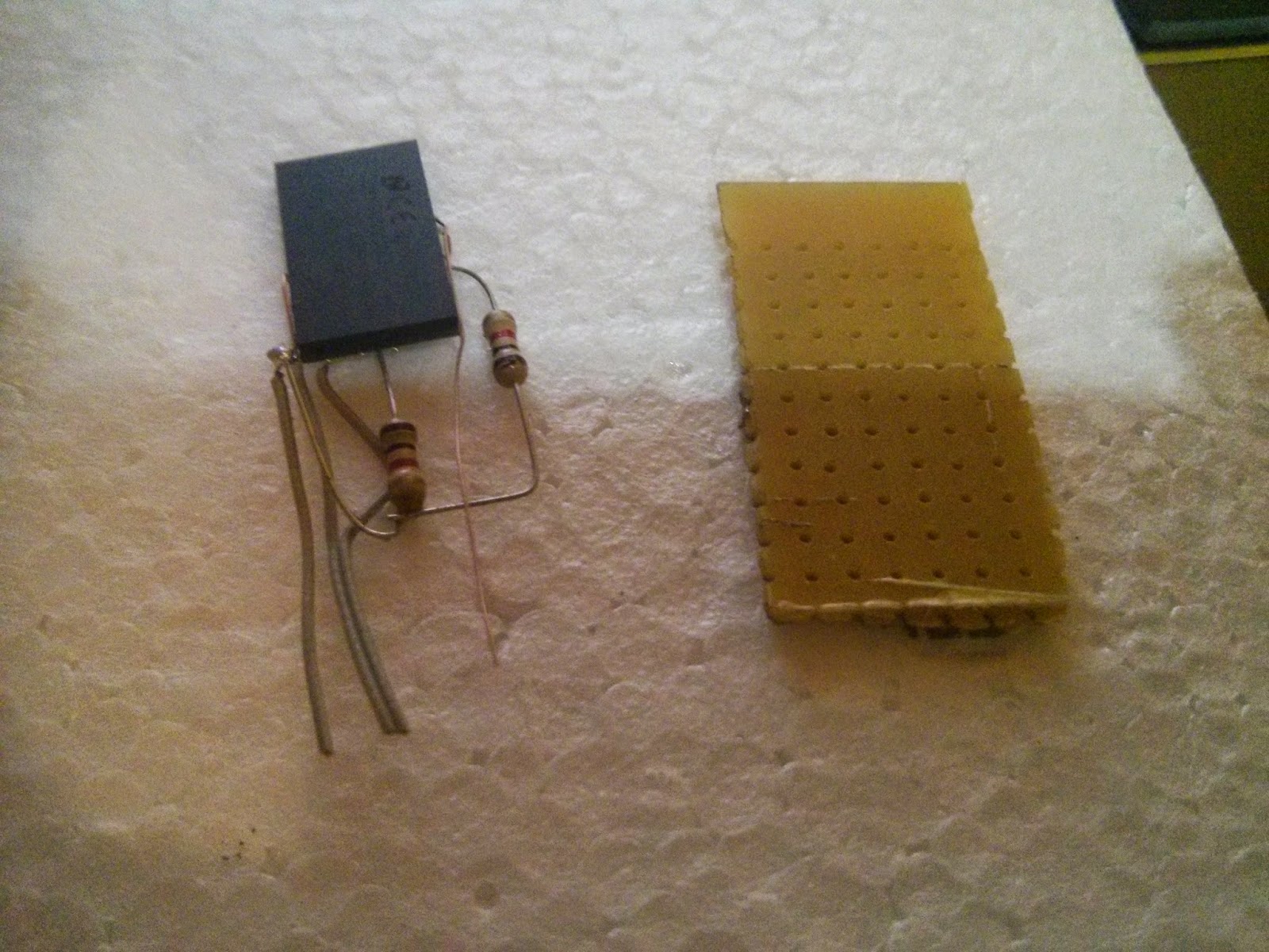
For the first step just grab everything required for the construction as listed in my  last post  Here are some of the pics for the module I got from TI image (Please mind my camera Nexus 4 isn't known for it's cam quality :P)


image image

Step 2  : Getting  Power Signals soldered


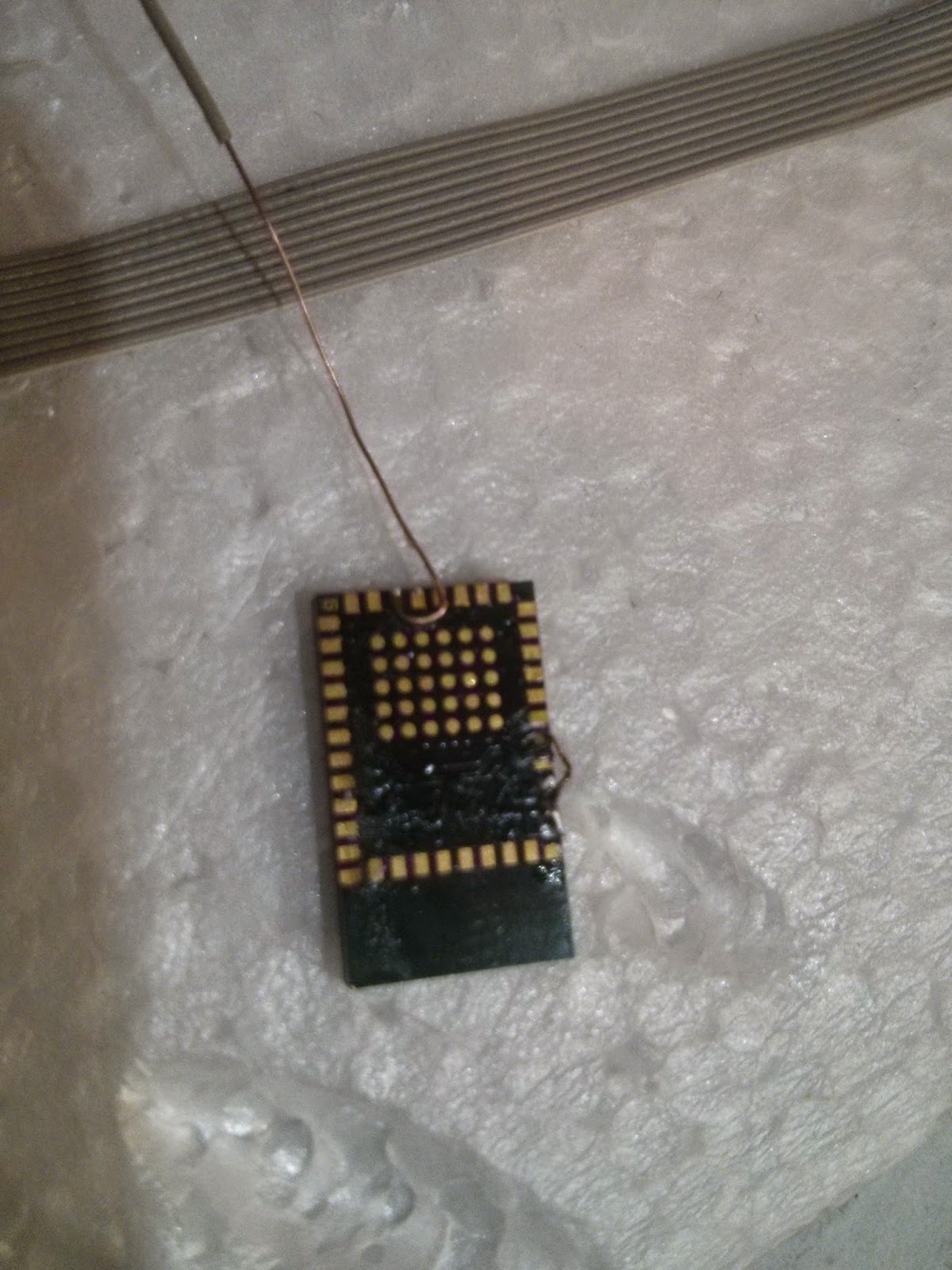
Firstly, apply flux to the entire pad array as shown in the picture below


http://1.bp.blogspot.com/-JZ_RcIwgLQY/VHDGTRbH5tI/AAAAAAAAHBk/JtjbNMrdveo/s1600/IMG_20141107_232604.jpghttp://1.bp.blogspot.com/-JZ_RcIwgLQY/VHDGTRbH5tI/AAAAAAAAHBk/JtjbNMrdveo/s1600/IMG_20141107_232604.jpgimage image


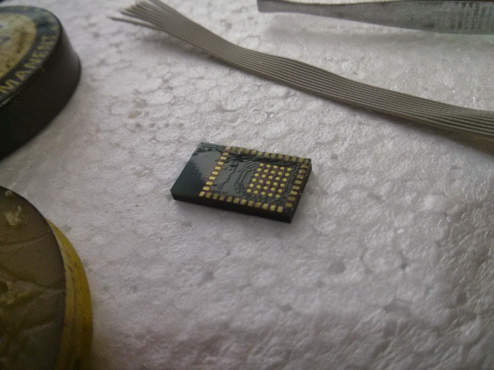
Then Solder the GND pins together. Further in the pictures below I have soldered the CTS pin to GND also, but I will recommend you guys to do it later once we are finished soldering the OP3 pin image


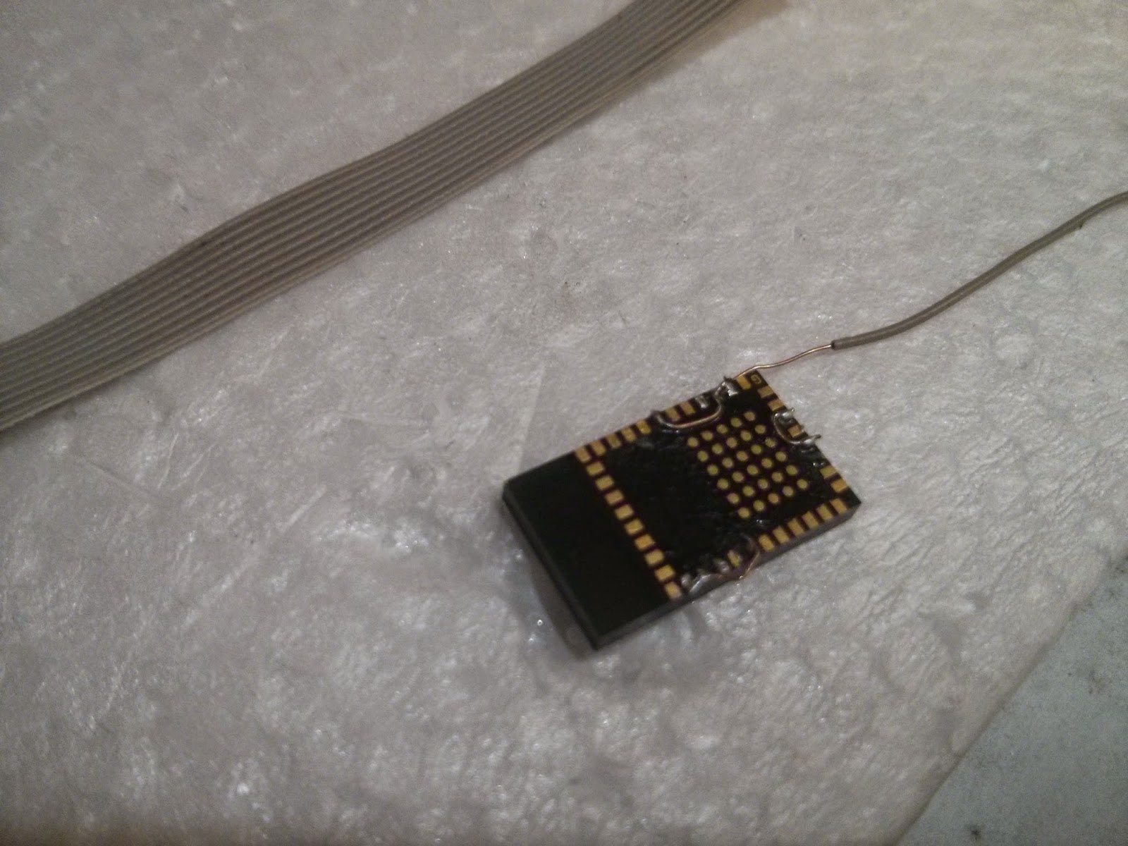
Also connect the 32Khz + pin to GND as suggested by TI . 


imageimage


Finally, solder the VCC signal, that is VCC+ V_Core as shown in the reference images in my previous post. Now we have the power supply up image , At this point grab a multimeter and check for shorts between VCC and GND image


imageimage


Step 3  :  Soldering other Important signals


In order for us to work with the module, we must first get the UART Signals set up :), as well as the Baud Rate select pins selected. You can change the communication Baud rate by tweaking the pins OP3, OP4 and OP5 in the below fashion,(I have used 9600 Baud by default)


OP3

OP4

OP5

Function

1

0

1

UART speed 9.6 kbps

1

1

0

UART speed 115.2 kbps

1

1

1

UART speed 921.6 kbps


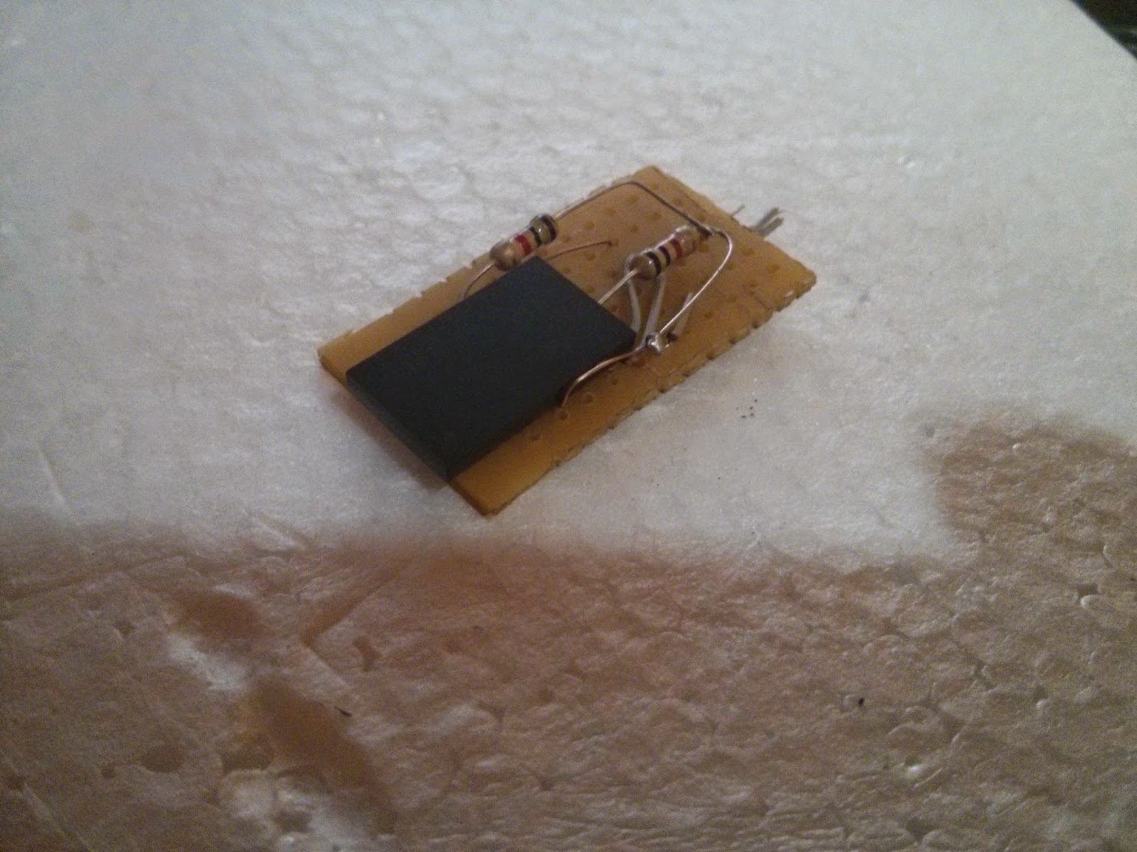
We will start by soldering 1K pull-up resistors to the respective OP3 and OP5 pins and will later connect them to the VCC pins.


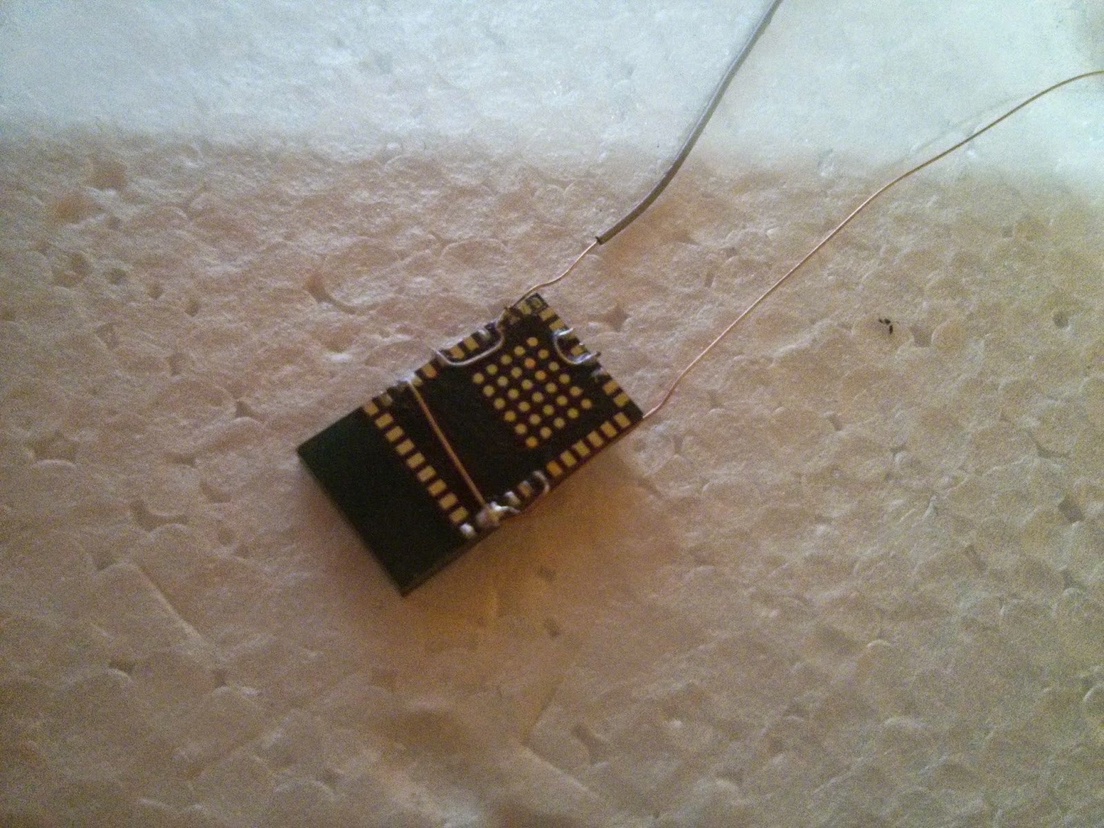
Meanwhile also connect some long wires to the Rx and the Tx pins of the module.


imageimage


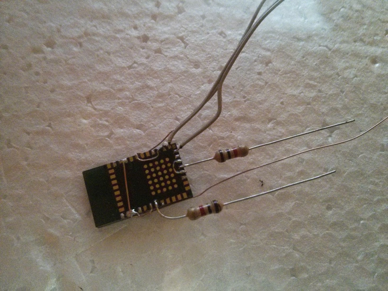
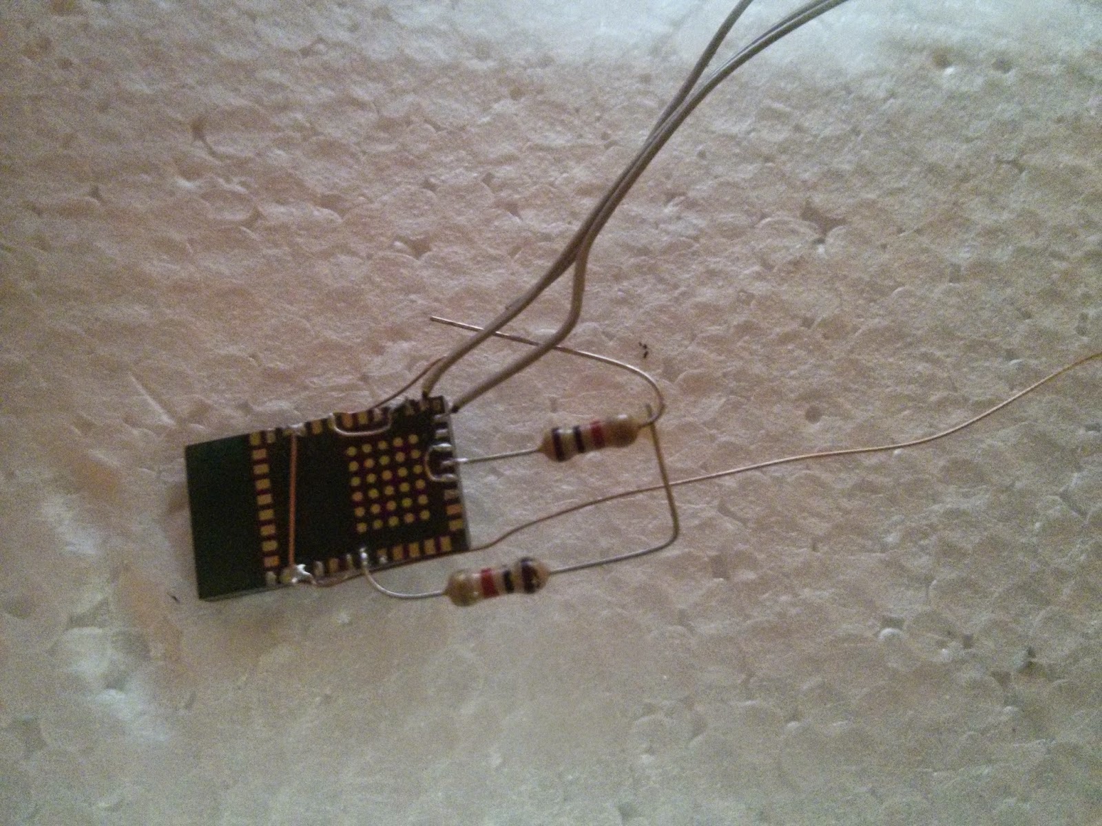
And some neat trick for connecting the resistors to VCC.


imageimage


After successfully connecting the resistors, now is a good time to connect the CTS pin to ground
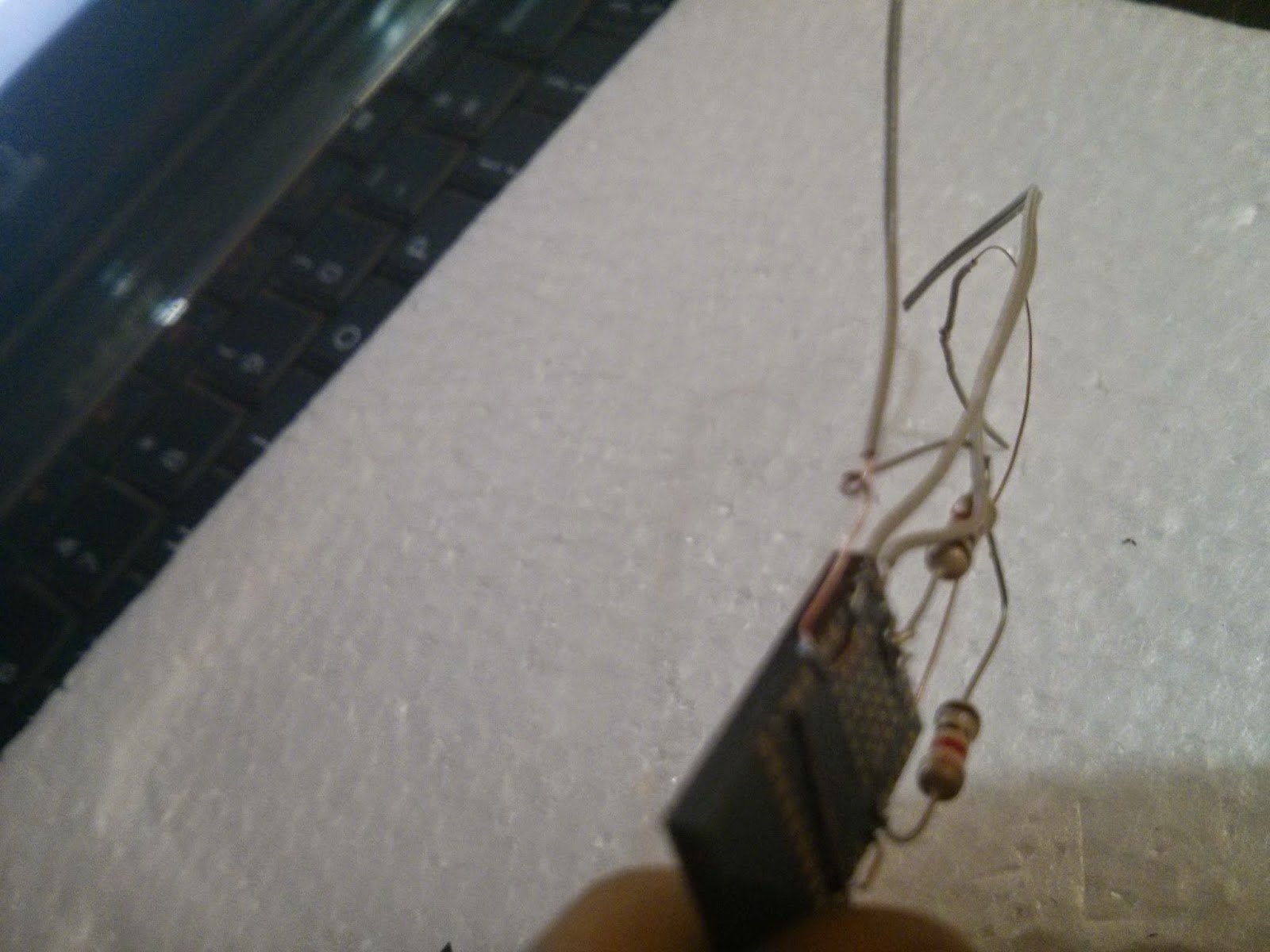
 image 

Now our module is almost ready image , to test : power on the module and check weather you get a "Serial Port Device" of some MAC Address in your Bluetooth scan list. If everything is fine, glue up the connections or simply add a double sided tape to firmly attach the wires hanging out :).


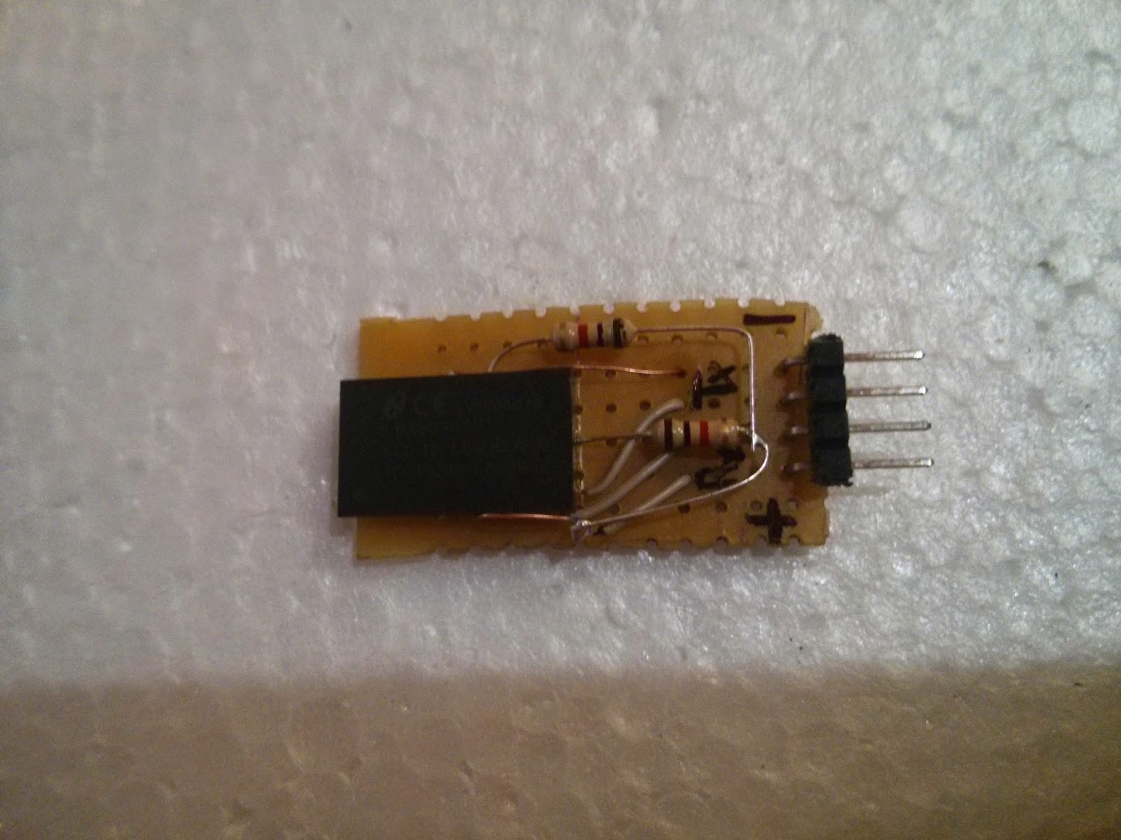
Step 4  :  Making the module


We now will build the base of the module and make this a plug and play module image .


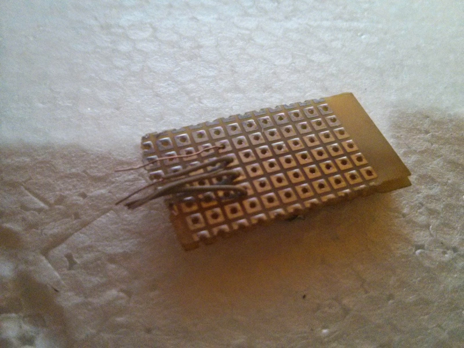
First, we will choose the corner of a prototyping PCB. and align the module in such a way that the upper part of the module till the horizontal pins do not come in contact or is near to the prototyping PCB copper pads.(The upper section of the Module is the Antenna and we should have some antenna clearance or else the signal from the module may be week.) as shown in the bottom images.


imageimage


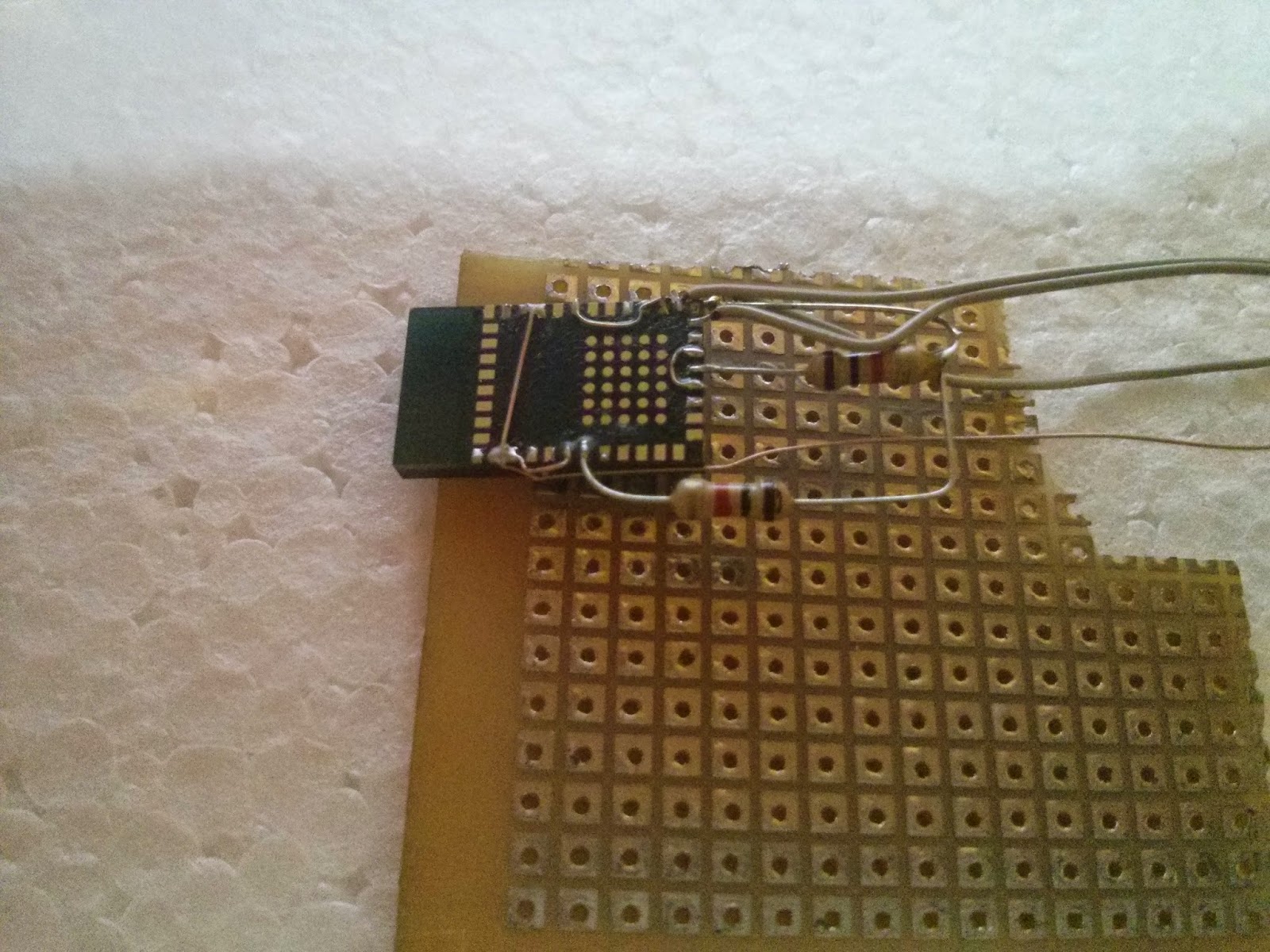
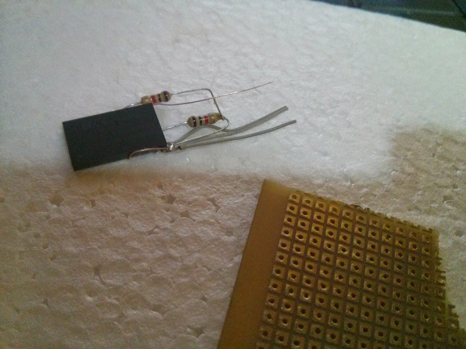
Then we cut  the amount prototyping PCB required for us. Always cut a bit more than required for margins image


imageimage


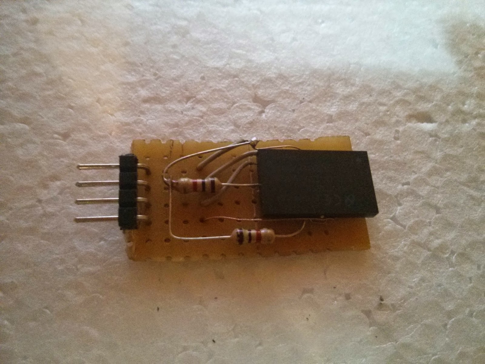
then we insert the VCC, GND Rx and Tx, wires through the holes and solder them to the PCB. Meanwhile, also solder 4pin 90dig 0.1" standard headers and connect the header to the signals.


imageimage


So, Our module is ready image image , I always forget what I do after couple of days image  so it's always a good idea to label each pin with a permanent marker :). Finally I also like to hot glue things up as sometimes if the double sided tape gets off the it's a problem image .


imageimage


NOTE : Handel the module very carefully through Step 4. As the wires as well as the pads are delicate. It so happened for me that while going through Step 4, I somehow broke the OP3 Pad from the module and the entire module was done image .


Step 5  : Testing the module


Well the easiest way to test is connecting it with an MSP430 Launchpad/Arduino/etc. and just do a serialPrint(Receving). You can use my Bluebot Project code for the MSP430 Launchpad here which already has that done. Visit my LMX9838 Module interfacing with MSP430 Launchpad post for further interfacing here. 


Some Important Tips for Soldering and construction 


Tip 1 : Always apply flux to the pad and tin the pad before soldering a wire to it.


Tip 2 : Always try and Short all the ground and power pins as few of them are sometimes regulator references and they are important to be connected to VCC. (Well check the datasheet for specific instructions)


Tip 3 : Always heat the pad a bit first before inserting the tin thread for better soldering (The Tin thread usually has flux on top of it which makes it easier that ways for sticking)


Tip 4 : Do Not HEAT the pad for larger duration as due to over heating, the pad may wear off/ or worst rip of image - That happened to me so take care .


Tip 5 : Always tend to use single stand thin wires with coating or extracted copper wires with coating image this saves loads of time and energy image


Regards,

Gurinder Singh Gill

Technervers.com

technervers.blogspot.com

  • Sign in to reply

Top Comments

  • gsgill112
    gsgill112 over 11 years ago in reply to shabaz +2
    Thanks @ shabaz , I use an Android mobile and for them I use either of these 2 App's BlueTerm or Bluetooth Serial Controller App the best part about the later is that you can lay a game-pad kind of button…
  • gsgill112
    gsgill112 over 11 years ago in reply to shabaz

    Thanks @shabaz, I use an Android mobile and for them I use either of these 2 App's BlueTerm or Bluetooth Serial Controller App the best part about the later is that you can lay a game-pad kind of button layout in the app and then control the bot. I was working on my BlueBot project for a local MakerSpace and that app was really handy image


    Regards,

    GurI

    • Cancel
    • Vote Up +2 Vote Down
    • Sign in to reply
    • More
    • Cancel
  • shabaz
    shabaz over 11 years ago

    Hi Gurinder,


    Nice in-the-air construction! And interesting device. I didn't know it existed.

    Any particular app you recommend for Android to use with this?

    • Cancel
    • Vote Up 0 Vote Down
    • Sign in to reply
    • More
    • Cancel
  • gsgill112
    gsgill112 over 11 years ago in reply to mcb1

    Thanks Mark, I have wood surface but just for the sake of pics i had to use thermocol. I am thinking of making my own tripod as I dont have a point to shoot can so i will do somethibg with a mobile case  imageAnd thanks once again for suggestions . imageimage

    • Cancel
    • Vote Up 0 Vote Down
    • Sign in to reply
    • More
    • Cancel
  • mcb1
    mcb1 over 11 years ago

    Nice work.

    An easy way to use something that would otherwise not be possible to connect.

    I should check mine since I can't use the USB in some applications.


    re photos

    Good cameras are essential for this.

    Macro lens or close up adaptor also helps, and a simple tripod or fixture will also help.

    A laminated white piece of A4 paper, or white card is a really handy reflector.


    Is that polystyrene you have as a work surface.?

    If it is, this is one of the worst for static, and not something I'd recommend for delicate electronics.


    Before static mats/material we used the old style linoleum  that you would put on the floor

    There is an instructable using a yoga mat and a sheet of foil.

    This is a relatively inexpensive model Static protection matStatic protection mat compared to destroying IC's and the time wasted to replace them.


    Mark

    • Cancel
    • Vote Up 0 Vote Down
    • Sign in to reply
    • More
    • Cancel
element14 Community

element14 is the first online community specifically for engineers. Connect with your peers and get expert answers to your questions.

  • Members
  • Learn
  • Technologies
  • Challenges & Projects
  • Products
  • Store
  • About Us
  • Feedback & Support
  • FAQs
  • Terms of Use
  • Privacy Policy
  • Legal and Copyright Notices
  • Sitemap
  • Cookies

An Avnet Company © 2025 Premier Farnell Limited. All Rights Reserved.

Premier Farnell Ltd, registered in England and Wales (no 00876412), registered office: Farnell House, Forge Lane, Leeds LS12 2NE.

ICP 备案号 10220084.

Follow element14

  • X
  • Facebook
  • linkedin
  • YouTube