element14 Community
element14 Community
    Register Log In
  • Site
  • Search
  • Log In Register
  • Community Hub
    Community Hub
    • What's New on element14
    • Feedback and Support
    • Benefits of Membership
    • Personal Blogs
    • Members Area
    • Achievement Levels
  • Learn
    Learn
    • Ask an Expert
    • eBooks
    • element14 presents
    • Learning Center
    • Tech Spotlight
    • STEM Academy
    • Webinars, Training and Events
    • Learning Groups
  • Technologies
    Technologies
    • 3D Printing
    • FPGA
    • Industrial Automation
    • Internet of Things
    • Power & Energy
    • Sensors
    • Technology Groups
  • Challenges & Projects
    Challenges & Projects
    • Design Challenges
    • element14 presents Projects
    • Project14
    • Arduino Projects
    • Raspberry Pi Projects
    • Project Groups
  • Products
    Products
    • Arduino
    • Avnet Boards Community
    • Dev Tools
    • Manufacturers
    • Multicomp Pro
    • Product Groups
    • Raspberry Pi
    • RoadTests & Reviews
  • About Us
  • Store
    Store
    • Visit Your Store
    • Choose another store...
      • Europe
      •  Austria (German)
      •  Belgium (Dutch, French)
      •  Bulgaria (Bulgarian)
      •  Czech Republic (Czech)
      •  Denmark (Danish)
      •  Estonia (Estonian)
      •  Finland (Finnish)
      •  France (French)
      •  Germany (German)
      •  Hungary (Hungarian)
      •  Ireland
      •  Israel
      •  Italy (Italian)
      •  Latvia (Latvian)
      •  
      •  Lithuania (Lithuanian)
      •  Netherlands (Dutch)
      •  Norway (Norwegian)
      •  Poland (Polish)
      •  Portugal (Portuguese)
      •  Romania (Romanian)
      •  Russia (Russian)
      •  Slovakia (Slovak)
      •  Slovenia (Slovenian)
      •  Spain (Spanish)
      •  Sweden (Swedish)
      •  Switzerland(German, French)
      •  Turkey (Turkish)
      •  United Kingdom
      • Asia Pacific
      •  Australia
      •  China
      •  Hong Kong
      •  India
      •  Korea (Korean)
      •  Malaysia
      •  New Zealand
      •  Philippines
      •  Singapore
      •  Taiwan
      •  Thailand (Thai)
      • Americas
      •  Brazil (Portuguese)
      •  Canada
      •  Mexico (Spanish)
      •  United States
      Can't find the country/region you're looking for? Visit our export site or find a local distributor.
  • Translate
  • Profile
  • Settings
Personal Blogs
  • Community Hub
  • More
Personal Blogs
Legacy Personal Blogs MicroPython #3: PWM, LED Fade
  • Blog
  • Documents
  • Mentions
  • Sub-Groups
  • Tags
  • More
  • Cancel
  • New
  • Share
  • More
  • Cancel
Group Actions
  • Group RSS
  • More
  • Cancel
Engagement
  • Author Author: navadeepganeshu
  • Date Created: 7 May 2020 3:50 PM Date Created
  • Views 1850 views
  • Likes 2 likes
  • Comments 3 comments
  • python 3.7
  • esp-8266
  • micropython
  • ideas_worth_sharing
Related
Recommended

MicroPython #3: PWM, LED Fade

navadeepganeshu
navadeepganeshu
7 May 2020

MicroPython

Pulse Width Modulation & Duty Cycles

image


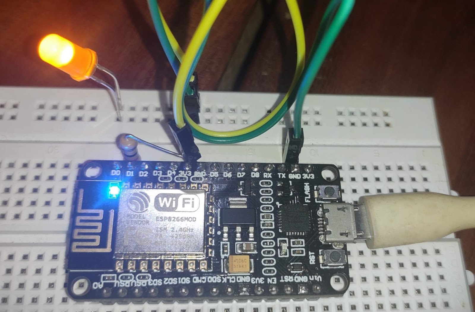
At the end of this, you will be able to implement PWM technique and see it on inbuilt LED in Pin2 of ESP 8266 and also by attaching external LED's. The whole process will be done by MicroPython programming. So, Let's begin with !


Note: You must have your MicroPython firmware pre-flashed onto your board before beginning with this. If not, follow up these before getting back here.


MicroPython #1: Introduction and Gearing Up


MicroPython #2: Triggering I/O's


Introduction to PWM & its concepts

Pulse Width Modulation(PWM) is a technique for getting analog results with digital means. Digital control is used to create a square wave, a signal switched between on and off. This on-off pattern can simulate voltages in between full-on (5 Volts) and off (0 Volts) by changing the portion of the time the signal spends on versus the time that the signal spends off. The duration of "on time" is called the pulse width. To get varying analog values, you change or modulate, that pulse width. If you repeat this on-off pattern fast enough with an LED, for example, the result is as if the signal is a steady voltage between 0 and 5v controlling the brightness of the LED.


image


Simply told, PWM is just varying the time on and time off of LED/ time high and time low of signal (0-3,3V here)


Implementation on ESP8266 (NodeMCU)

Using MicroPython PWM can be easily implemented and you will be able to get signals with different duty cycle based on frequency and delay set. Let's go through then !


The algorithm goes as follows :


> Import the Pin on the device to your program using 'from machine import Pin'.

MicroPython says, " Hey Pin 2 there on ESP 8266, someone is calling you. Come on! "

Also, call PWM class here with 'import pin, PWM'.


> Call the time


" Hey clock, help me in knowing the time/delay ".


With the help of time, you can turn LED on and off. Call time with 'from machine import sleep'. time.sleep(<delay>) is used to set delay.


> Set frequency for PWM cycles with 'frequency = x' and then set Pin number and call frequency as declared above.


> Now, it's all about repeating the cycle. We have already set factors and made declarations. 

for i in range (<initial>, <final>, <step size>):

Here, we'll need only <final limit> and <Initial value> in these 3 factors and others will be taken '1' by default. Giving a range of analog values, 0-1023+1 (10 bit) within a for loop, ranging will be possible with default intervals of 1.

Putting these functions in while loop, it will be possible to visualise Fade in LED attached to Pin 2.

Below is the MicroPython script for the same:
---------------------------
from machine import Pin,PWM
from time import sleep
frequency = 5000
led = PWM(Pin(2), frequency)
while True:
     for duty_cycle in range(0, 1024):
       led.duty(duty_cycle) sleep(0.005)

----------------------------

Get this written and run the script. There there !

You will find Pin 2 LED fading with declared Interval. Try changing interval, frequency, delay and you'll find something interesting !


image
LED with Minimum and Maximum Brightness


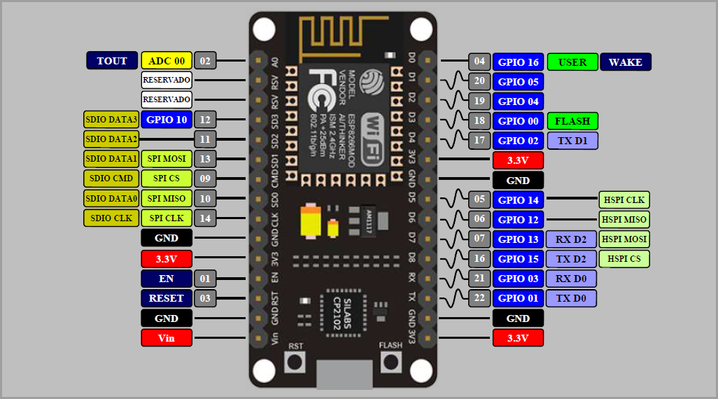
LED's can also be attached to any of the other GPIO's and the same function can be achieved in 10-bit resolution. Change the Pin number (line4) of the source code


The pin assignment is in the format GPIO(x) and not Pin(x) of ESP8266.

(Ex: Pin 17 (D4) is GPIO 2 which we declare as Pin(2) in code)


Reference Schematic:

image


Summary: All of the above proves the power of MicroPython and shows its simplicity compared to C++ / Embedded C. Now, we have a fading LED. Why not we use this to control BLDC, Steppers, Pump etc, Integrate to make flashing and fading LED's,............and what not ??


Just drop down your comments, troubles or any bugs you found on the way in reaching so far in the comment section below.
GitHub link for source codes: https://github.com/NavadeepGaneshU/CL3VERTRONICS

Hope you followed up things tight.

Spark something

Cheers !!!


  • Sign in to reply

Top Comments

  • colporteur
    colporteur over 5 years ago +1
    Great technical tutorial. During my early electronic training, I was fascinated how human anomalies we taken advantage of. An example is how the frequency of a digital signal can effect the way the eye…
  • colporteur
    colporteur over 5 years ago in reply to navadeepganeshu

    Both my brain and eyes are old. I tend to see flicker even when it is not there. I think the pilot light in my head might be going out:)

    • Cancel
    • Vote Up 0 Vote Down
    • Sign in to reply
    • More
    • Cancel
  • navadeepganeshu
    navadeepganeshu over 5 years ago in reply to colporteur

    Very true.
    All of that depends on the response time of the eyes/brain which is unique for each.

    • Cancel
    • Vote Up 0 Vote Down
    • Sign in to reply
    • More
    • Cancel
  • colporteur
    colporteur over 5 years ago

    Great technical tutorial.

    image

    During my early electronic training, I was fascinated how human anomalies we taken advantage of. An example is how the frequency of a digital signal can effect the way the eye sees things. If you apply a digital signal with a frequency of less than 30Hz, the LED light will appear to flicker (waveforms A). The absence of light during the off cycle is picked up by the human eye as flicker.


    The frequency rate of 30Hz that creates flicker is not a fixed value. Human eyes and brains are unique; Some people may not see a flicker at a frequency of less than 30Hz, and others (me!–Sean) do.


    Increase the frequency above 30Hz, the eyes persistence retains the light over a short period of time (waveforms B). The eye sees the LED light on but doesn’t see the LED off because it occurs to fast.


    Increase the frequency above 30Hz (waveforms C) and reduce the duty cycle (pulse width), the higher frequency takes advantage of the eyes persistence. The LED is turning on and off but the human eye sees the light on but dimmer.

    • Cancel
    • Vote Up +1 Vote Down
    • Sign in to reply
    • More
    • Cancel
element14 Community

element14 is the first online community specifically for engineers. Connect with your peers and get expert answers to your questions.

  • Members
  • Learn
  • Technologies
  • Challenges & Projects
  • Products
  • Store
  • About Us
  • Feedback & Support
  • FAQs
  • Terms of Use
  • Privacy Policy
  • Legal and Copyright Notices
  • Sitemap
  • Cookies

An Avnet Company © 2025 Premier Farnell Limited. All Rights Reserved.

Premier Farnell Ltd, registered in England and Wales (no 00876412), registered office: Farnell House, Forge Lane, Leeds LS12 2NE.

ICP 备案号 10220084.

Follow element14

  • X
  • Facebook
  • linkedin
  • YouTube