The objective of this project is to design and build a microcontroller-based Mood Light using an inexpensive tri-colour RGB LED. You will be the envy of all your friends once they see this awesome and futuristic mood light in operation. No not really!! But you may become popular and the talking-point with your friends when you convert this simple LED project into the High-Powered 3W RGB Lamp Project which is the subject of a follow-on article. This particular article will enable you to learn about handling interrupts and pulse width modulation (PWM) techniques using an inexpensive LED device and some standard E-Blocks.
I bet you can’t wait to get started on this particular project as it’s so cool.
The mood light uses an array of three light emitting diodes that are supplied encapsulated in a conventional LED plastic package. They are capable of projecting red, green and blue light. The three lights are connected to three bits on the PIC’s output port and by using a pulse width modulation (PWM) technique the time that each light is switched-on can be controlled. This means that theoretically all possible colours can be produced. To get the best effect the tri-colour LED should be fitted inside a diffuser to spread the light around.
A matrix keypad is used to control the operation of mood light as described below.
The mood light has the capability to:
• Mix the individual colours.
• Save the colour settings as set of “favourites” in the PIC’s EEPROM.
• Clear the “favourites” settings
• Display a pre-programmed rainbow effect.
• Reset all the colours to their off condition.
Components that you will need include:
• PIC Microcontroller (PIC16F88/PIC16F1937) and Multiprogrammer board (EB006) / Or your favourite Arduino board and E-blocks adapter shield
• Matrix keypad (EB014)
• Prototyping board (EB016) or Terminal board (EB002)
• Kingbright – Full Colour LED Lamp 5mm High Brightness (Rapid part number 72-9641)
• Plastic/Polystyrene/PingPongBall diffuser
• 2-off 100 ohm ΒΌ watt resistors
• 1-off 150 ohm ΒΌ watt resistor
• Connecting wire, etc;
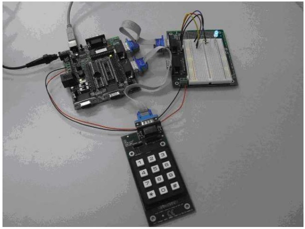
As this simple circuit takes very little time to assemble it is ideal for beginners. First of all make sure the EB006 PICmicro microcontroller board is fitted with a 16F1937 or 16F88 device. Next connect the Keypad board to Port-B and the Prototyping board or the Terminal board to Port-A. You may find that you need an IDC cable to connect these boards to the EB006 programming board. Using the following photograph as a guide, mount the Tri-Colour LED on the prototyping board. A 150 ohm and two 100 ohm resistors need to be connected from the Tri-Colour LED to the terminal area that connects (via the IDC cable) to Port-A.
At the base of the Tri-Colour LED there is a flat edge that is used to identify pin-1, which is the connection that operates the “red” LED. The 150 ohm resistor needs to be connected to pin-1 and from there to A2 on the port connector. The next pin (pin-2) is the common cathode which needs to be connected to ground. The next pin (pin-3) is the connection that drives the “Blue” LED. A 100 ohm resistor needs to be connected from this pin to A0 on the port connector. The final pin (pin-4) is the connection that drives the “green” LED. The second 100 ohm resistor needs to be connected from this pin to A1 on the port connector. That completes the assembly of the hardware.
The top row of keys (on the keypad) is used to increase the amount of illumination for each of the RGB parts of the Tri-Colour LED. Key [1] controls “red”, Key [2] controls “green” and Key [3] controls “blue”. The second row of keys decreases the amount of illumination. The keys on the third row enable you to save your favourite colour settings. Key [7] is labelled “Favourite 1”, Key [8] is “Favourite 2” and Key [9] is “Favourite 3”. The final row of keys are used to operate the rainbow effect using Key [*], to reset the favourites using Key [0] or to reset the colour mixes to zero using Key [#].
The “Main” part of the Flowcode program is fairly straightforward consisting of a user macro to scan the keypad and another user macro to decode the keypad. The decode program contains twelve decision icons that lead off to dedicated pieces of Flowcode that implement the various keypad functions as described above.
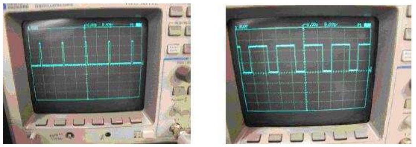
There are three important variables called “red”, “green” and “blue” that define the amount of illumination for each of the colours. This information is used with a simple pulse width modulation technique that controls the mark-space ratio for how long each of the Tri-Colour LEDs are turned-on and turned-off. The two photographs below show some examples of different mark-space ratios as depicted on an oscilloscope.
The PWM part of the program is controlled completely by an interrupt that is triggered whenever TMR0 (i.e. timer-0) overflows. When you design a PWM system the first thing you need to decide
upon is the repetition frequency for one complete cycle and how many sub-divisions there will be. This will affect the range of mark-space ratios that can be accommodated. The Mood Light described here uses a switching frequency of 72Hz and divides each cycle into 8 slots labelled slot-0 to slot-7. By comparing the value of the variables “red”, “green” and “blue” with the slot value a decision can be made whether to turn the appropriate LED on or off. A value of 0 will keep an LED turned-off for all eight slots, while a value of 1 will turn an LED for just the first slot (i.e. slot-0). A value of 7 will keep an LED illuminated for all 8 slots which delivers maximum illumination.
As this design makes use of the 8MHz internal oscillator the following calculations are applicable. If you decide to use a different device (like the 16F628A) or make use of an external crystal or series resonator, then you will need to modify the following calculations to achieve the correct frequency and number of slots.
When the 8MHz internal oscillator is used this will generate a clocking frequency of 2MHz which equates to a clock period of 0.5uS. The switching frequency of 72Hz equates to a cycle time of 13888.888uS which means that each slot has a width of 1388uS. So you need to generate an interrupt from TMR0 every 1388uS. This can be achieved by setting the Prescaler to divide the internal clock by 16. This will give an interrupt every 2048uS when TMRO overflows from 255 to 0.
0.5uS * 16 * 256 = 2048uS
Obviously this period is too long, but it can be shorten in the interrupt program by forcing TMR0 to start counting from 82 rather than zero. As there are 174 steps or increments from 82 until TMR0 overflows (at 256) this gives a period of 1392uS.
0.5 * 16 * 174 = 1392uS (which is very close to the target value of 1388uS)
The interrupt service routine (ISR) associated with TMR0 has three tasks to do. Force TMR0 to 82 (or -174 as -174 is the 2β€s complement of 82); switch the appropriate LED beam on to generate the PWM mark-space ratio; and finally increment the value of the “slot” counter.
The attached Flowcode program should enable you to create a fully working Mood Light with the tri-colour LED connected via Port-A and a 3 by 4 line keypad connected to Port-B.
By recreating the E-blocks circuitry using veroboard or protoboard you can greatly reduce the size of the mood light circuitry allowing it to fit inside an enclosure and go on working for a long time. The E-blocks datasheets all have schematic diagrams showing the components you need and the wiring.


Top Comments