


Motor control module or M.C.M. for short is part of Stingray project responsible for controlling two motors that
move entire tank. This module generates two PWM signals to M.P.M. , with I already described on my blog ,
and communicates with two encoders via I2C bus. So here are schematics of it
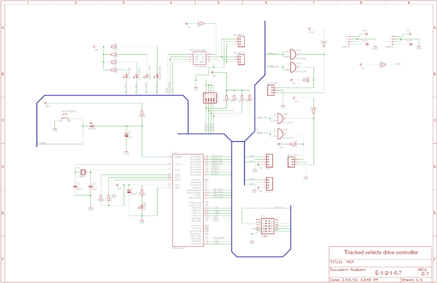
As you can see just like with M.P.M. there's nothing uncommon in this design but this one is a little more complex
so I will give more detailed explanation of its parts and their function.
Heart of circuit is ATMEGA16 that sends pwm signal via 74LS03N NAND gate to M.P.M. module.
Other functions of this microcontroller are communication with other modules via RS-485 bus and gathering
info about motors speed with help of I2C encoders. Main function of those NAND gates is to provide additional
buffer between microcontroller and elements that work under heavy load. As for RS-485 i used LTC485CN8#PBFLTC485CN8#PBF transceiver
and part of device address can be manually set with dip-switch.
As I wrote in my last post there were a few silly things in previous versions of this schematic , for example I overcomplicated
reset controller for no apparent reason and we were trying to use our own programmer connector that would disable some
function of this device. I decided to drop that idea because similar solution proved to be very problematic in use in my other project
and as for reset control I simplified it as much as i could.
For some reason preparing this post took me 3 days , I found it hard to say something interesting about device and no to repeat things
that are obvious after looking at schematic. I'm sending gerbers to my nearest circuit board producer and in meantime will work on
software. I'm also working on much simpler robot , a line-follower that I plan on making from what lays around in workshop , so