


In a previous blog post I resurrected an EHX Electric Mistress flanger effect pedal after acquiring just the PCB off someone on the Electro Harmonix forum. This is a great pedal that has a sweet sound however there is one issue that affects all Electric Mistresses that were manufactured prior to the Deluxe Mistress which was brought out in the mid 80's, and that is they suffered a 10% to 15% drop in volume when you engage the effect. This is so annoying and has been the bane of Mistress owners lives for years. There are many work arounds, some people solder in a resistor and a tantlium capacitor at the output stage which does solve the issue but really just boosts the dry unaffected sound leaving the wet flanged sound where it was. Therefore the flanged sound is 10% quieter than the dry so the mix is wrong.
Just for clarity here's the Mistress Schematic just for reference.

In that other Blog post Jon Clift suggested changing the output resistor to a larger size from 470 to 910.... I not 100% keen on doing that. this PCB is over 40 years old, and I don't want to start mucking around with the tracks too much. Already in one part of the PCB the tin has started lifting and part of a track has gone totally. These things are fragile so I don't want to start removing components and re-soldering then removing again, then re-soldering again. I have however posted that suggestion on a pedal forum in the hope that someone else might give it a go, and someone has given an answer which is below:
Increasing the resistor will increase the level, true. But your numbers are off, because you are ignoring the 47n capacitor to ground. Its impedance is roughly 3,4k at 1kHz. So the level drop is less than you state, and doubling the resistor won't give double the volume. The problem is by changing the resistor value you also shift the lowpass frequency of the filter that is formed by the three resistors and the capacitor to a higher frequency. You basically get a treble boost. But the output treble filter must match the pre-filter network around IC1B in front of the SAD, or you won't get an even response.
You can try a small increment, but I doubt you will get it to what you will perceive as unity without making it sound trebly or harsh.
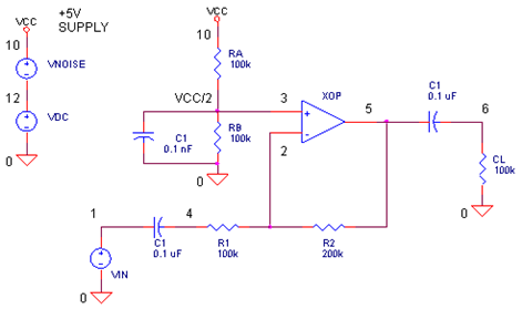
Some people have solved the issue by installing a separate boost stage before the output jack socket thereby boosting the whole volume to compensate, one solution is to install an inverting Op-Amp booster like the one below. This was suggested by a fellow in a pedal forum as a booster circuit to install inside the enclosure wired into the Mistress PCB output stage.
This got me thinking that maybe I should just build a pedal to run externally of the Mistress to boost the volume when I engage the effect. you see I'm lucky in so far as all my pedals run through an audio switcher. The switcher is a series of loops, each effect is in a loop and all effects are turned on, i have a foot pedal on the floor that selects what loop I want to engage, so rather than turning the actual effect on and off, i just engage or disengage the appropriate loop...... The Electric Mistress is in a loop on its own, therefore there's no reason why I can't place a separate booster pedal after the Mistress in the same loop. Therefore when I engage that particular loop both pedals are on at the same time. This is a good work around as it's not changing the circuit of the Mistress, thus keeping the sound of the pedal as originally intended. It also gives me a new pedal to build so win win  This is also the method used by David Gilmour, he uses a Lehle Parallel Boost pedal after the Mistress to compensate for the volume drop.

David Gilmours stage rig with the Electric Mistress and the Lehle booster to compensate for the volume drop
After reviewing the above schematic I started the search for for a suitable clone booster to build. I eventually found a pedal called the MXR Micro Amp. By adding a preset amount of gain with just a single control, the Micro Amp is a great way to boost your signal for lead work or adjust between two different guitars with unmatched output (i.e. hum buckers to single-coils). It can also provide a permanent boost in a long effects chain where signal drop off is a problem. This seemed to be the best solution, not only was it a boost, it was clean...... super clean therefore it doesn't colour the sound. Just what I needed, and simple to boot. I scoured the internet for a clone of the MXR and found one on General Guitar Gadgets, the schematic is below:


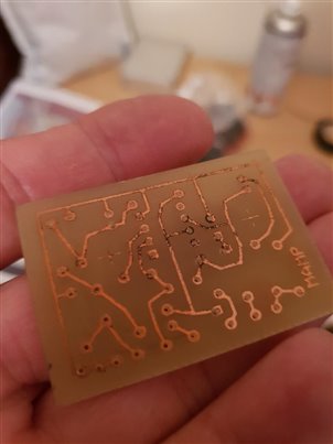
This circuit isn't much different to the other one above, but it is the official MXR schematic so i'll go with this one. For this project i'll be scanning and etching my own PCB, as it's only a small board it shouldn't be that hard to get a good etch. The whole build should fit easily into a Hammond 1590B enclosure. A white one has been ordered, so it'll look very similar to a genuine MXR pedal. I've also downloaded a hi-res copy of the MXR logo to put on the case. The PCB board layout is freely available on the General Guitar Gadgets website so I won't detail it here, however I can show you my effort at etching this board. It's tiny, and to be honest some of the drilled holes may not be exactly in the middle of the solder pads, but hey..... It cost me next to nothing so I'll give it a go.
Drilled PCB |
The board was made from a scrap piece of PCB off cut I had laying around. I used the laser transfer method, so consequently you are getting some black residue left on the tracks from the ink. This won't as you well know affect the end result. However, there is one pad where the hole was drilled way off centre...... This may cause an issue so I may make one more board just in case this one fails. I'd like to experiment with other types of board manufacture. I did try the photo resist method and it failed miserably..... Maybe I just did it all wrong. I might give that method another go as I still have all the stuff to use for that method.
Another method that has been highly recommended is the "Press & Peel" method. This looks really good but sooooo expensive for what it is. I've checked EBay and a single 216 x 279mm sheet is around £5!!! Is it really worth the money? I don't know, but a gentleman in Australia, Michael Dempsey who was helping me with the Power boost issue the other year highly recommended it, and he makes PCB's commercially.
I need to invest in a small PCB drill. I'm drilling these with a full size cordless drill with a 0.8mm drill bit. Not ideal, but necessary under the circumstances. Maybe a Dremel type hand tool would be better on a small drill press type stand.... It doesn't need to be all singing and dancing as i'll only use it for drilling PCBs.
And I still need to buy an Oscilloscope........ They're expensive and at the moment i can't warrant spending the money as I have other more important family commitments to pay for. Maybe a second hand one off EBay?? Thoughts?? If I did go the second hand route, what should i look for (being a total noob with scopes). What should the minimum specification be that I'm looking for, and is there any real advantage in digital over analogue. I've noticed that the likes of John Wiltrout and Jon Clift both use a digital scope, they look good but are expensive. The analogue scopes look old, and to some they are retro and cool....... But are they any good for a nooby like me, or should i go the digital route from the get go? Are there limitations with an analogue scope against a digital scope? it's a minefield, and I need advice. maybe this is a sensible question for another forum post..... I'll do one.
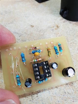
Next on the agenda....... Populate the board. |
So, I started populating the board and got to the last 2 components only to find i don't have them in my stockpile of resistors...... production has been brought to a halt while i get them.
Top Comments