element14 Community
element14 Community
    Register Log In
  • Site
  • Search
  • Log In Register
  • Community Hub
    Community Hub
    • What's New on element14
    • Feedback and Support
    • Benefits of Membership
    • Personal Blogs
    • Members Area
    • Achievement Levels
  • Learn
    Learn
    • Ask an Expert
    • eBooks
    • element14 presents
    • Learning Center
    • Tech Spotlight
    • STEM Academy
    • Webinars, Training and Events
    • Learning Groups
  • Technologies
    Technologies
    • 3D Printing
    • FPGA
    • Industrial Automation
    • Internet of Things
    • Power & Energy
    • Sensors
    • Technology Groups
  • Challenges & Projects
    Challenges & Projects
    • Design Challenges
    • element14 presents Projects
    • Project14
    • Arduino Projects
    • Raspberry Pi Projects
    • Project Groups
  • Products
    Products
    • Arduino
    • Avnet & Tria Boards Community
    • Dev Tools
    • Manufacturers
    • Multicomp Pro
    • Product Groups
    • Raspberry Pi
    • RoadTests & Reviews
  • About Us
  • Store
    Store
    • Visit Your Store
    • Choose another store...
      • Europe
      •  Austria (German)
      •  Belgium (Dutch, French)
      •  Bulgaria (Bulgarian)
      •  Czech Republic (Czech)
      •  Denmark (Danish)
      •  Estonia (Estonian)
      •  Finland (Finnish)
      •  France (French)
      •  Germany (German)
      •  Hungary (Hungarian)
      •  Ireland
      •  Israel
      •  Italy (Italian)
      •  Latvia (Latvian)
      •  
      •  Lithuania (Lithuanian)
      •  Netherlands (Dutch)
      •  Norway (Norwegian)
      •  Poland (Polish)
      •  Portugal (Portuguese)
      •  Romania (Romanian)
      •  Russia (Russian)
      •  Slovakia (Slovak)
      •  Slovenia (Slovenian)
      •  Spain (Spanish)
      •  Sweden (Swedish)
      •  Switzerland(German, French)
      •  Turkey (Turkish)
      •  United Kingdom
      • Asia Pacific
      •  Australia
      •  China
      •  Hong Kong
      •  India
      • Japan
      •  Korea (Korean)
      •  Malaysia
      •  New Zealand
      •  Philippines
      •  Singapore
      •  Taiwan
      •  Thailand (Thai)
      • Vietnam
      • Americas
      •  Brazil (Portuguese)
      •  Canada
      •  Mexico (Spanish)
      •  United States
      Can't find the country/region you're looking for? Visit our export site or find a local distributor.
  • Translate
  • Profile
  • Settings
Personal Blogs
  • Community Hub
  • More
Personal Blogs
Legacy Personal Blogs NXP 74AXP1G57 review
  • Blog
  • Documents
  • Mentions
  • Sub-Groups
  • Tags
  • More
  • Cancel
  • New
  • Share
  • More
  • Cancel
Group Actions
  • Group RSS
  • More
  • Cancel
Engagement
  • Author Author: RWM
  • Date Created: 31 May 2014 8:52 PM Date Created
  • Views 1079 views
  • Likes 0 likes
  • Comments 2 comments
  • logic
  • high-speed
  • 74axp1g57
  • measurement
  • nxp
  • configurable
Related
Recommended

NXP 74AXP1G57 review

RWM
RWM
31 May 2014

NXP was so nice to send me demo board of 74AXP1G57. It is configurable, 3-input digital logic device. Can act as AND, EXNOR, inverter, buffer etc. Power supply is in 0.7-2.75V range, however I checked also voltages below lower limit. Demo board has 4 ICs:

image

In order to check dynamic behaviour, I connected 3 gates configured as inverters to form ring oscillator. Results are below:

1) supply voltage 0.6V (so lower than stated in datasheet; below stable oscillations were not possible):

image

Frequency generated was about 600kHz, so transition time of each gate was about 275ns. Wave is not symmetrical due to internal structure of gate.


2) supply voltage 0.65V:

image

Frequency increased to about 1.8MHz (3 times), so transition time of each gate was about 94ns. Wave is still not symmetrical due to internal structure of gate.


3) supply voltage 0.7V (minimum supply voltage specified for this logic gate):

image

Frequency increased to about 3.4MHz (2 times), so transition time of each gate was about 49ns. Wave is still not symmetrical due to internal structure of gate.


4) supply voltage 0.8V:

image

Frequency increased to about 8.6MHz (over 2 times), so transition time of each gate was about 19ns. Symmetricity of wave improved..


5) supply voltage 0.9V:

image

Frequency increased to about 14.5MHz (nearly 2 times), so transition time of each gate was about 11.5ns. Symmetricity of wave is nearly perfect.


6) supply voltage 1.0V:

image

Frequency increased to about 21MHz (about 1.5 times), so transition time of each gate was about 8.1ns. Symmetricity of wave is nearly perfect.


7) supply voltage 1.2V:

image

Frequency increased to about 32MHz (about 1.5 times), so transition time of each gate was about 5.1ns. Symmetricity of wave is nearly perfect.


8) supply voltage 1.5V:

image

Frequency increased to about 50MHz (about 1.5 times), so transition time of each gate was about 3.3ns. Symmetricity of wave is perfect.


9) supply voltage 1.8V:

image

Frequency increased to about 61MHz (about 1.2 times), so transition time of each gate was about 2.7ns. Symmetricity of wave is nearly perfect.


10) supply voltage 2.5V:

image

Frequency increased to about 77MHz (about 1.2 times), so transition time of each gate was about 2.2ns. Symmetricity of wave is nearly perfect.


11) supply voltage 2.75V:

image

Frequency increased to about 80MHz (about 1.05 times), so transition time of each gate was about 2.1ns. Symmetricity of wave is nearly perfect. Rise and fall times are relatively slow (about 3.1 ns at period time 12.6 ns), so wave looks like sinusoidal. Where is the source of such behaviour? Wave was measured using standard oscilloscope probe:

image

This probe has long ground connection, which has substantial inductance. In order to improve measurement results it is needed to remove probe tip and use short ground connection:

image

Rise and fall times improved substantially - from 3.1 ns to about 2 ns:

image

Output waveforms of all 3 outputs:

image

You can see easily transitions between gates.


Applications


1. Light sensor


I needed to design light sensor for luminance measurement for low voltage system. As most sensors have supply voltage limit 2.7V or 1.8V and I needed 1.5V, I was in a need to design low voltage sensor. It is also possible to use photodiode, amplifier and ADC input, but this was not possible.


I designed this sensor using 74AXP1G57 configurable logic, photoresistor and capacitor. This simple oscillator generates wave with light-dependent frequency. Variable frequency digital signal can be easily interfaced with low voltage MCU.


Board:

image

Schematic:

image

Few results:

Illuminance [lx]
Output frequency [Hz]
16528
731746
1002215
1001

10220

It is versatile, energy-efficient solution. You can change measurement range by selecting other photoresistor type and output frequency range by changing capacitor. For reliable measurements, capacitor should be good quality (C0G ceramic or foil). Output frequency change vs. illuminance is not linear, but can be easily approximated by MCU.


2. PhotoSound


It is designed for fun, I combined two light-dependent generators using Ex-NOR gate to intermodulate output waves. So it is possible to obtain nearly 0 Hz frequency (if both generators have the same frequency) or some beat frequency (up to hearing limit).


Board:

image

Schematic:

image

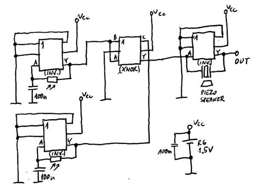
Using demo board, two resistors: R5 and R11 must be removed.


You can have fun playing PhotoSound!


You don't have permission to edit metadata of this video.
Edit media
x
image
Upload Preview
image

  • Sign in to reply
Parents
  • Problemchild
    Problemchild over 11 years ago

    A fun device, wasn't sure how you selected the logic function there Ryszard?

    Also I presume they are infering it fit's in tot he 74 series logic family from it's name ?

    • Cancel
    • Vote Up 0 Vote Down
    • Sign in to reply
    • More
    • Cancel
  • RWM
    RWM over 11 years ago in reply to Problemchild

    Hi John,


    74AXP1G57 is a configurable device, you can select different functions:

    image

    Internal structure:

    image

    Datasheet:

    http://www.nxp.com/documents/data_sheet/74AXP1G57.pdf


    Function depends on inputs connection.I used 2 functions: inverter and XNOR:

    image

    Inverters with Schmitt input are used in generators, output signals go to mixer (based on XNOR) and then to push-pull speaker driver (based on inverter).


    Markings of this family members is based on standard 74xx family, e.g. 74AXP1G06 is a single inverter with open drain (so like single gate from 7406). owever, this family is compatible with low voltage logic (from 0.8V±0.1V to 2.5V±0.25V).

    • Cancel
    • Vote Up 0 Vote Down
    • Sign in to reply
    • More
    • Cancel
Comment
  • RWM
    RWM over 11 years ago in reply to Problemchild

    Hi John,


    74AXP1G57 is a configurable device, you can select different functions:

    image

    Internal structure:

    image

    Datasheet:

    http://www.nxp.com/documents/data_sheet/74AXP1G57.pdf


    Function depends on inputs connection.I used 2 functions: inverter and XNOR:

    image

    Inverters with Schmitt input are used in generators, output signals go to mixer (based on XNOR) and then to push-pull speaker driver (based on inverter).


    Markings of this family members is based on standard 74xx family, e.g. 74AXP1G06 is a single inverter with open drain (so like single gate from 7406). owever, this family is compatible with low voltage logic (from 0.8V±0.1V to 2.5V±0.25V).

    • Cancel
    • Vote Up 0 Vote Down
    • Sign in to reply
    • More
    • Cancel
Children
No Data
element14 Community

element14 is the first online community specifically for engineers. Connect with your peers and get expert answers to your questions.

  • Members
  • Learn
  • Technologies
  • Challenges & Projects
  • Products
  • Store
  • About Us
  • Feedback & Support
  • FAQs
  • Terms of Use
  • Privacy Policy
  • Legal and Copyright Notices
  • Sitemap
  • Cookies

An Avnet Company © 2026 Premier Farnell Limited. All Rights Reserved.

Premier Farnell Ltd, registered in England and Wales (no 00876412), registered office: Farnell House, Forge Lane, Leeds LS12 2NE.

ICP 备案号 10220084.

Follow element14

  • X
  • Facebook
  • linkedin
  • YouTube