


Introduction
Even more oscillators!
At some point, for reasons I can't remember now, I tried simulating some simple sine wave
oscillators. At the time they all got left in the simulator's default save directory which is where
I've been retrieving them from.
The last blog looked at a very simple and, to be honest, not very good single-transistor design
Transistors: Phase-Shift Sine Wave Oscillator
This one, in contrast, uses op-amps to provide the gain and produces a somewhat better
sine wave out. As with the previous blog the circuit came from a book, though I've taken it and
adapted it for 5V single-supply operation using just the very cheapest-of-cheap quad op-amps. This
one has an interesting feature in that it produces two sine waves rather than one. The two are in
quadrature (90 degrees apart) - that naturally results from part of the circuit functioning as an
integrator, something which I'll look at later.
I found this oscillator in the IC Op-Amp Cookbook by Walter Jung [1]. It obviously wasn't original to
him, another slightly different version appears in a later book by Scott Hamilton [2] and he gives
references for it that go back to the 1950s.
Here's the circuit as Jung published it
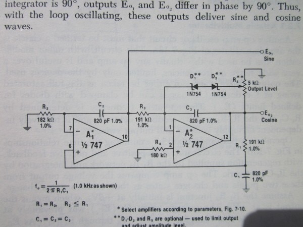
I reduced the resistor values by a factor of about ten, increased the capacitors by a factor of ten,
and used an op amp to generate an artificial ground to get the following circuit that I built on a
breadboard and will then be the basis for simulating the circuit.

I should say that, although it does work, in some ways it's something of a fragile design and it's
quite easy to choose values that won't start to oscillate on a breadboard, sometimes even when the
simulation shows that it does, so some care is needed with it.
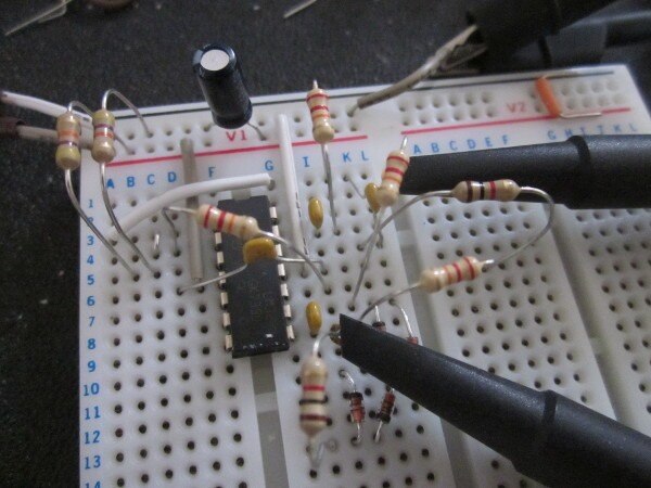
Breadboard
Here it is built on a breadboard
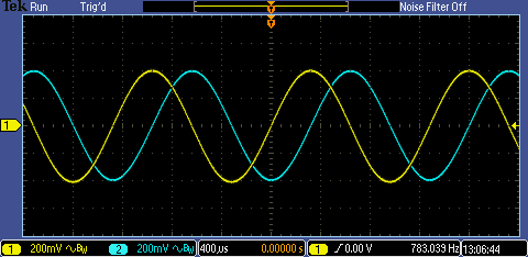
here are the 'scope traces showing the sine waves at the outputs of U2 (blue trace) and U3 (yellow trace)
and here is an FFT of the blue trace (U2 output)
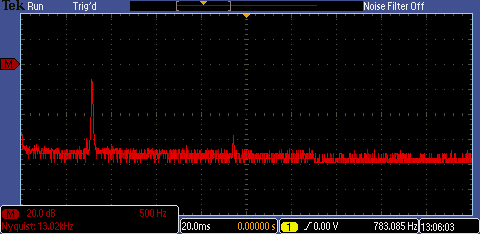
so, just the fundamental and a small amount of third harmonic before we're into the 'scope's noise.
Maybe a couple of percent THD. Not too bad, though nothing like the performance of a good Wien-bridge
oscillator circuit.
How Does It Work ?
U1 is generating an artificial ground midway between 0V and 5V (ie at 2.5V). It works simply as a
buffer (a voltage follower) with the voltage derived from a potential divider made up of R4 and R5.
The input impedance is very high (simply that of the non-inverting input of the op amp) and hardly
loads the divider at all. In contrast, the output impedance is very low. Although the open-loop
output of the op-amp might be a figure like hundred ohms or so, the negative feedback reduces that to
well under an ohm as long as the device has plenty of gain (it does) and we're operating within the
capabilities of the op amp, i.e. within its output voltage range and within its ability to sink and
source current.
That then means we effectively have a circuit operating on a +2.5/-2.5 supply with a ground in the
middle in a very similar way to if we genuinely had a dual-rail supply.
The heart of the oscillator is U2 and U3, and it's this section of the diagram we need to look at to
understand how the oscillator works.
U3 functions as an inverter and an integrator. The inverter gives us 180 degrees of phase shift over
a fairly wide range. The integrator gives 90 degrees, again over a fair range. It's this stage that
gives us the two sinewaves 90 degrees apart.
U2 has two RC networks. Each will result in a phase variation with frequency and it's this variation
that determines the frequency of oscillation. When each results in a phase shift of approximately 45
degrees, the total round the loop will be 90 degrees for the U2 stage and a further 270 for the U3
stage, giving a net 360 degrees right round the loop, which is what we require for sustained
oscillation.
The Simulation
If I set the simulator going for a transient analysis, it generates these waveforms
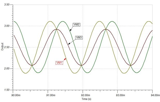
That predicts a frequency of oscillation of 709Hz. That's quite a long way from the physical circuit
which measured 783Hz. Some of that will be down to component variation, the capacitors are probably
only 10%, but there are other effects making things difficult for us which we'll see in a moment with
an open-loop approach.
Right. So how do I look at this open-loop? The way I'm doing it here is an experiment and I'm a
little unsure about it, so don't take this as a tutorial. It seems to give plausible results, so is
worth looking at.
Here is the circuit reworked. (Note that I've swapped around the voltage meters, so don't go by the
previous circuit when you look at the Bode plots.)

What I've done is to insert ridiculously large values of inductors and capacitors to modify the circuit so
that at dc the loop is closed and the simulator can find the dc operating points that it needs prior
to doing the Bode plots, but at ac the loop is open and driven by the generator with the response
through to each meter being measured without the loop being closed and oscillating. (I'd love to be
able to claim credit for thinking of this, but actually I stole the idea from a TI document on
simulating the feedback of an op amp [3].)
Here's the phase plot
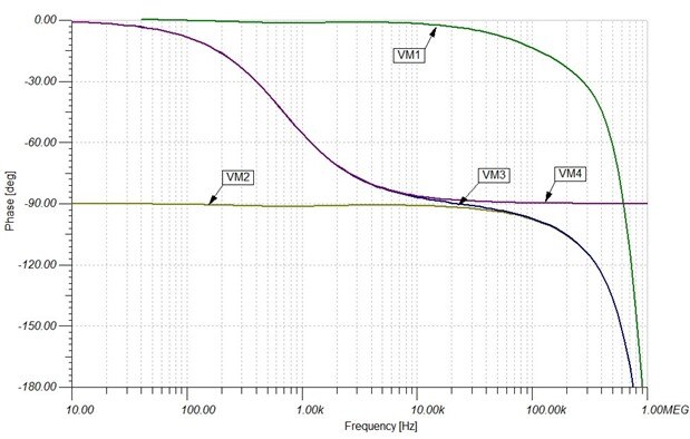
That clearly shows the integrator working nicely, keeping VM1 and VM2 90 degrees apart (up to about 10kHz).
We can also see the way that the two frequency selective networks vary with frequency. The point at
which VM3 reaches 45 degrees is 690Hz, which isn't too far off the closed-loop simulation oscillation
frequency of 709Hz. Above 10kHz, VM3 and VM4 start to diverge. The op amp is trying to drive C1/R1 so
that the non-inverting input matches the inverting input; 10kHz is the point where it can no longer
manage that, presumably because of slew rate limitations. This plot is for a very small signal, so
those effects will manifest themselves much more in the closed-loop simulation with its larger voltage
swings and that is probably part of the reason for the difference in predicted frequency of
oscillation between the two. The other factors that confuse things a bit are that the op amps have a
small delay, slew rate limitations give some delay, and the mechanism for limiting the amplitude - the
diodes and resistor - modify the phase slightly, so all-in-all the oscillation point won't be exactly
at the 45 degree point.
Now here's the magnitude plot (gain relative to the generator at the input)
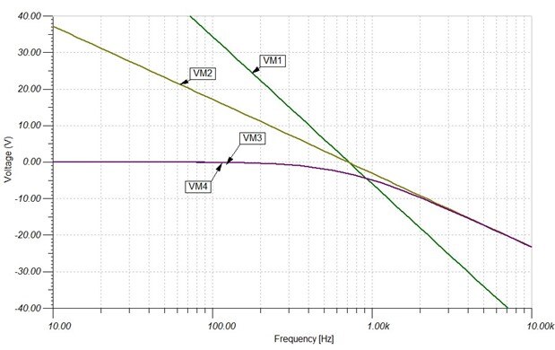
This shows the way the RC networks roll off (the 'knee' comes where the phase is transitioning
between the low frequency and high frequency values). At the 45 degree point, the gain of the RC
network is one over root two down, but the effect of the action of U2 is that the networks counter
each other to give a gain out of unity at that point. The integrator gain has also fallen to unity at
that frequency, and that results in a gain of one round the loop at the oscillation frequency.
Actually, at the oscillation frequency, the integrator gain is a fraction above unity and the RC
networks a fraction below, so the frequency isn't quite where the two meet, though it's close.
Because it's all so finely balanced, if we had all the RC networks the same, there would be a real
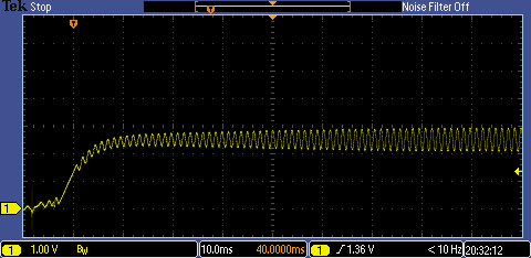
possibility that it wouldn't start up, so to deal with that I made R24 23k rather than 22k. That has
this effect on the breadboard circuit:
with R24=22k
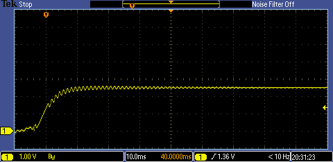
now with R24=23k
That all makes predicting the precise frequency of oscillation from the open-loop response somewhat
complicated even though the criteria for oscillation is quite simple (unity gain and 360 degrees
phase shift).
I hope that was of some interest. It's taken me a bit further along the road to understanding
simulation, so I'm benefiting from all this, even if it is a bit of a struggle to understand at
times.
[1] IC Op-Amp Cookbook by Walter Jung. Howard W. Sams & Co. First edition 1974.
[2] An Analog Electronics Companion by Scott Hamilton. CUP. First edition 2003.
[3] Analog Engineer's Pocket Reference. TI. See page 50. https://www.ti.com/seclit/ml/slyw038b/slyw038b.pdf
Top Comments
-

shabaz
-
Cancel
-
Vote Up
+3
Vote Down
-
-
Sign in to reply
-
More
-
Cancel
-

jc2048
in reply to shabaz
-
Cancel
-
Vote Up
+4
Vote Down
-
-
Sign in to reply
-
More
-
Cancel
Comment-

jc2048
in reply to shabaz
-
Cancel
-
Vote Up
+4
Vote Down
-
-
Sign in to reply
-
More
-
Cancel
Children