element14 Community
element14 Community
    Register Log In
  • Site
  • Search
  • Log In Register
  • Members
    Members
    • Benefits of Membership
    • Achievement Levels
    • Members Area
    • Personal Blogs
    • Feedback and Support
    • What's New on element14
  • Learn
    Learn
    • Learning Center
    • eBooks
    • STEM Academy
    • Webinars, Training and Events
    • Learning Groups
  • Technologies
    Technologies
    • 3D Printing
    • FPGA
    • Industrial Automation
    • Internet of Things
    • Power & Energy
    • Sensors
    • Technology Groups
  • Challenges & Projects
    Challenges & Projects
    • Design Challenges
    • element14 presents
    • Project14
    • Arduino Projects
    • Raspberry Pi Projects
    • Project Groups
  • Products
    Products
    • Arduino
    • Dev Tools
    • Manufacturers
    • Raspberry Pi
    • RoadTests & Reviews
    • Avnet Boards Community
    • Product Groups
  • Store
    Store
    • Visit Your Store
    • Choose Another Store
      • Europe
      •  Austria (German)
      •  Belgium (Dutch, French)
      •  Bulgaria (Bulgarian)
      •  Czech Republic (Czech)
      •  Denmark (Danish)
      •  Estonia (Estonian)
      •  Finland (Finnish)
      •  France (French)
      •  Germany (German)
      •  Hungary (Hungarian)
      •  Ireland
      •  Israel
      •  Italy (Italian)
      •  Latvia (Latvian)
      •  
      •  Lithuania (Lithuanian)
      •  Netherlands (Dutch)
      •  Norway (Norwegian)
      •  Poland (Polish)
      •  Portugal (Portuguese)
      •  Romania (Romanian)
      •  Russia (Russian)
      •  Slovakia (Slovak)
      •  Slovenia (Slovenian)
      •  Spain (Spanish)
      •  Sweden (Swedish)
      •  Switzerland(German, French)
      •  Turkey (Turkish)
      •  United Kingdom
      • Asia Pacific
      •  Australia
      •  China
      •  Hong Kong
      •  India
      •  Korea (Korean)
      •  Malaysia
      •  New Zealand
      •  Philippines
      •  Singapore
      •  Taiwan
      •  Thailand (Thai)
      • Americas
      •  Brazil (Portuguese)
      •  Canada
      •  Mexico (Spanish)
      •  United States
      Can't find the country/region you're looking for? Visit our export site or find a local distributor.
  • Translate
  • Profile
Personal Blogs
  • Members
  • More
Personal Blogs
Legacy Personal Blogs Phase Shift Correction: It Takes Two
  • Blog
  • Documents
  • Mentions
  • Sub-Groups
  • Tags
  • More
  • Cancel
  • New
Blog Post Actions
  • Subscribe by email
  • More
  • Cancel
  • Share
  • Subscribe by email
  • More
  • Cancel
Group Actions
  • Group RSS
  • More
  • Cancel
Engagement
  • Author Author: cookmesomekai
  • Date Created: 6 Oct 2020 8:44 PM Date Created
  • Views 857 views
  • Likes 6 likes
  • Comments 3 comments
  • hioki
  • power analyzer
  • current sensor
  • power analysis
Related
Recommended

Phase Shift Correction: It Takes Two

cookmesomekai
cookmesomekai
6 Oct 2020

Phase shift correction in power analysis is like dancing a tango: it takes two – the power analyzer supporting the function as well as a suitable sensor with a known phase delay. If one of them is missing… well… just imagine that tango…


You don't have permission to edit metadata of this video.
Edit media
x
image
Upload Preview
image


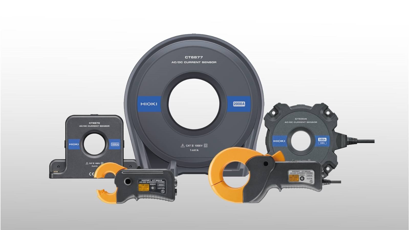
Using shunts to measure currents in power analysis might be an option for small currents, but when you look at measuring currents above 50A then typically current sensors come into play. However, every current sensor in the world produces a gradually increasing phase error in the high-frequency region due to group delays of the circuitry. Additionally, differences in the design of various sensor models cause the magnitude of this error to vary. A phase shift correction function allows to compensate this error. To make such a phase shift correction function work properly you need two things:

  • A power analyzer making the correct calculations in its software
  • A current sensor with a known phase shift


A good way to explain the calculations in the power analyzer software is by comparing it to the “deskew” function of an oscilloscope: If two different signals arrive at the oscilloscope at different times due to latencies then the “deskew” function lets you align those signals by compensating the latency with a fixed time value.


image


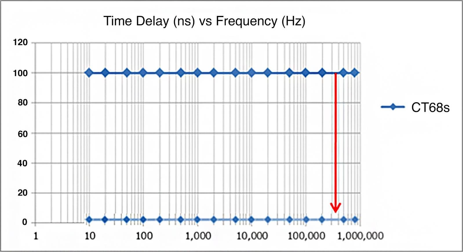
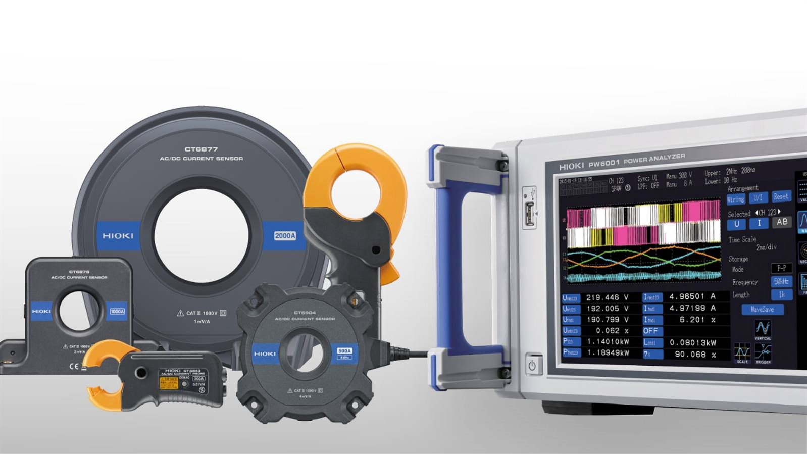
When you enter the phase shift correction value in a power analyzer like HIOKI’s PW6001 then you basically do the same thing because phase shift is essentially a time delay between current and voltage. As an example, here is how this delay looks for a HIOKI CT68 series current sensor. The time delay is shown in nanoseconds against the frequency:


image


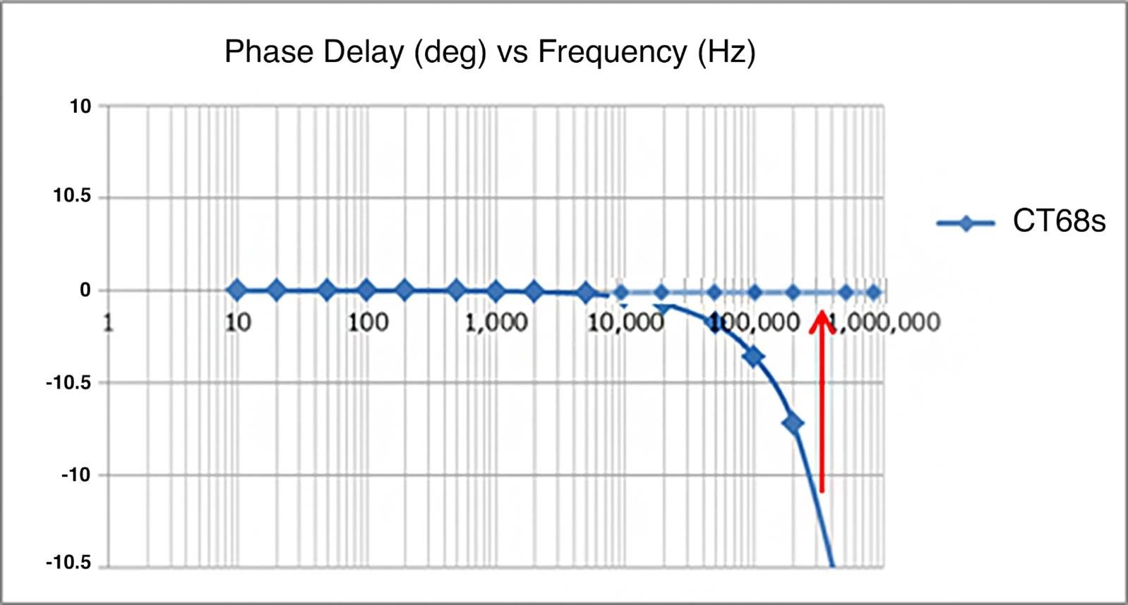
100ns delay at 100Hz doesn’t have the same impact as 100ns delay at 1MHz. This becomes clear when translating the above time delay into phase delay values described in degrees:


image


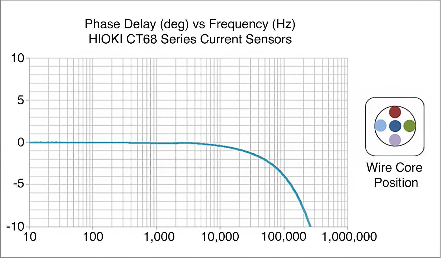
To make things as straight forward as above of course you need a current sensor where the time delay is the same regardless of the frequency. With HIOKI current sensors like the CT68 series this is the case so coming back to the deskew function you only need one value to compensate the phase shift of the sensor.


This is one of the things that makes HIOKI sensors special – but it is not standard for current sensors currently on the market. Here is what would happen with a typical current sensor:


image


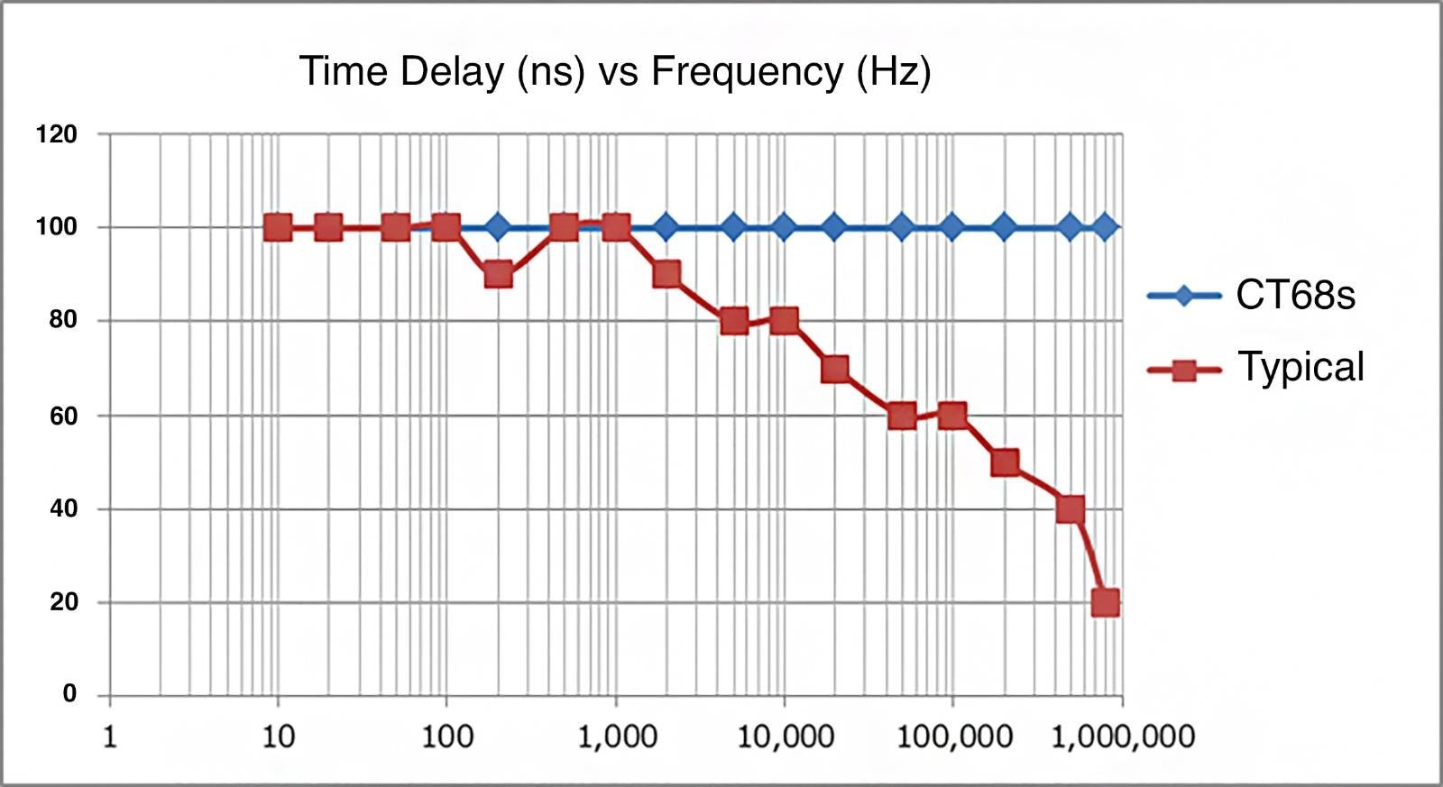
A sensor where the time delay values are different depending on the frequency will make the phase shift compensation in a power analyzer much more difficult. Because which value do you use as your “deskew” parameter?


image


Another thing that makes HIOKI current sensors special is that for the phase delay it is not relevant where your wire core is located within the sensor when you make the measurement:


image


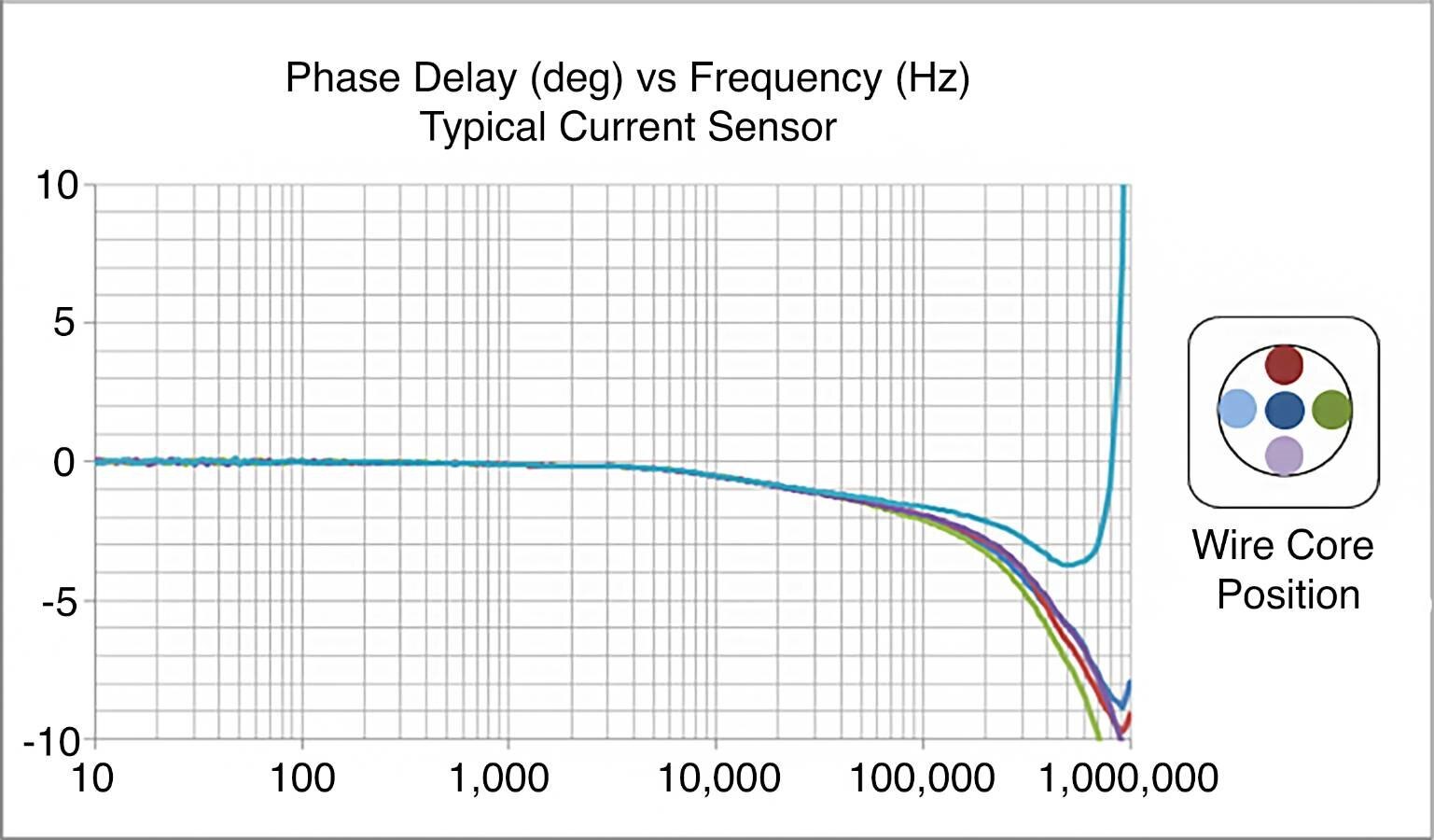
The reason why you can only see one single line in the chart is because the phase delay curves for all five measurement positions are the same. Again, this is not a standard feature for current sensors on the market. Typically, the position of the wire core within the sensor does make a difference as you can see in the below graph:


image


As you can see there is no phase shift compensation without a power analyzer to support the feature. But as you can also see only the combination of power analyzer and suitable current sensor allows you to perform a proper phase shift compensation in your measurements.


HIOKI has been concentrating on making sensors for power measurement for many years so time delay characteristics have always been a focus point for HIOKI’s engineers. At the same time sensors from other manufacturers are typically only designed for accurate (DC) current sensing where phase delay characteristics are less important.


image


Therefore HIOKI power analyzers together with HIOKI current sensors are the perfect combination for your wide-band power analysis applications from DC to high frequency. Because like with a tango it takes two...


If you would like to download this article as a PDF then it is available in five languages:

  • English (original)
  • French
  • German
  • Spanish
  • Italian


The German version has also been published in German by the tech monthly "Elektronikpraxis".


For a really technical "deep-dive" into phase shift correction especially when evaluating the efficiency of motor drive systems then check out this technical article.


And if at this point you still want to know more about this topic then please feel free to message me.

  • Sign in to reply
  • three-phase
    three-phase over 2 years ago in reply to cookmesomekai

    Hello Kai,


    The injection test set I am referring to is something like an Omicron CMC356 or CMC256, or the SMRT series of instruments from Megger. To give it its full title, it is a Secondary Current Injection Test Set, often abbreviated to SCITS. They come with a variety of output configurations, but they can all inject voltage and current to test protection relays and transducers in switchgear.


    SCITS units are usually quite accurate, so I can usually measure the performance of a power meter using a SCITS, by varying the voltage, current and phase angle. At the other end, if I have a very accurate power analyser, I can use that to verify that the output of the SCITS is within parameters, hence may interest in the PW6001.


    Kind regards,


    Donald.

    • Cancel
    • Vote Up 0 Vote Down
    • Sign in to reply
    • More
    • Cancel
  • cookmesomekai
    cookmesomekai over 2 years ago in reply to three-phase

    Hi Donald,


    Thanks for the kind feedback. I'm sorry I don't understand: what do you mean with "injection test set"?


    Kind regards


    Kai.

    • Cancel
    • Vote Up 0 Vote Down
    • Sign in to reply
    • More
    • Cancel
  • three-phase
    three-phase over 2 years ago

    Good concise explanation of the issue and the solution. That power analyser looks to have a lot of capability built in, would be interesting to test one out with an injection test set.


    Kind regards.

    • Cancel
    • Vote Up 0 Vote Down
    • Sign in to reply
    • More
    • Cancel
element14 Community

element14 is the first online community specifically for engineers. Connect with your peers and get expert answers to your questions.

  • Members
  • Learn
  • Technologies
  • Challenges & Projects
  • Products
  • Store
  • About Us
  • Feedback & Support
  • FAQs
  • Terms of Use
  • Privacy Policy
  • Legal and Copyright Notices
  • Sitemap
  • Cookies

An Avnet Company © 2023 Premier Farnell Limited. All Rights Reserved.

Premier Farnell Ltd, registered in England and Wales (no 00876412), registered office: Farnell House, Forge Lane, Leeds LS12 2NE.

ICP 备案号 10220084.

Follow element14

  • Facebook
  • Twitter
  • linkedin
  • YouTube