element14 Community
element14 Community
    Register Log In
  • Site
  • Search
  • Log In Register
  • Community Hub
    Community Hub
    • What's New on element14
    • Feedback and Support
    • Benefits of Membership
    • Personal Blogs
    • Members Area
    • Achievement Levels
  • Learn
    Learn
    • Ask an Expert
    • eBooks
    • element14 presents
    • Learning Center
    • Tech Spotlight
    • STEM Academy
    • Webinars, Training and Events
    • Learning Groups
  • Technologies
    Technologies
    • 3D Printing
    • FPGA
    • Industrial Automation
    • Internet of Things
    • Power & Energy
    • Sensors
    • Technology Groups
  • Challenges & Projects
    Challenges & Projects
    • Design Challenges
    • element14 presents Projects
    • Project14
    • Arduino Projects
    • Raspberry Pi Projects
    • Project Groups
  • Products
    Products
    • Arduino
    • Avnet Boards Community
    • Dev Tools
    • Manufacturers
    • Multicomp Pro
    • Product Groups
    • Raspberry Pi
    • RoadTests & Reviews
  • Store
    Store
    • Visit Your Store
    • Choose another store...
      • Europe
      •  Austria (German)
      •  Belgium (Dutch, French)
      •  Bulgaria (Bulgarian)
      •  Czech Republic (Czech)
      •  Denmark (Danish)
      •  Estonia (Estonian)
      •  Finland (Finnish)
      •  France (French)
      •  Germany (German)
      •  Hungary (Hungarian)
      •  Ireland
      •  Israel
      •  Italy (Italian)
      •  Latvia (Latvian)
      •  
      •  Lithuania (Lithuanian)
      •  Netherlands (Dutch)
      •  Norway (Norwegian)
      •  Poland (Polish)
      •  Portugal (Portuguese)
      •  Romania (Romanian)
      •  Russia (Russian)
      •  Slovakia (Slovak)
      •  Slovenia (Slovenian)
      •  Spain (Spanish)
      •  Sweden (Swedish)
      •  Switzerland(German, French)
      •  Turkey (Turkish)
      •  United Kingdom
      • Asia Pacific
      •  Australia
      •  China
      •  Hong Kong
      •  India
      •  Korea (Korean)
      •  Malaysia
      •  New Zealand
      •  Philippines
      •  Singapore
      •  Taiwan
      •  Thailand (Thai)
      • Americas
      •  Brazil (Portuguese)
      •  Canada
      •  Mexico (Spanish)
      •  United States
      Can't find the country/region you're looking for? Visit our export site or find a local distributor.
  • Translate
  • Profile
  • Settings
Personal Blogs
  • Community Hub
  • More
Personal Blogs
Legacy Personal Blogs PID on a EK-TMC4C123GXL Evaluation Board. Part 2: The Hardware.
  • Blog
  • Documents
  • Mentions
  • Sub-Groups
  • Tags
  • More
  • Cancel
  • New
  • Share
  • More
  • Cancel
Group Actions
  • Group RSS
  • More
  • Cancel
Engagement
  • Author Author: jc2048
  • Date Created: 11 Mar 2017 10:17 PM Date Created
  • Views 725 views
  • Likes 3 likes
  • Comments 3 comments
Related
Recommended

PID on a EK-TMC4C123GXL Evaluation Board. Part 2: The Hardware.

jc2048
jc2048
11 Mar 2017

Part 1 can be found here:


PID on a EK-TMC4C123GXL Evaluation Board. Part 1: Getting started.


At this point I had to decide what to try and control. I wanted something that would be slow enough that the processor could keep up, but fast enough that it would present at least some kind of a challenge. In the end I decided to do that most traditional of things, the one that everyone does with a new processor board, I'd light an LED. Here's the LED


image


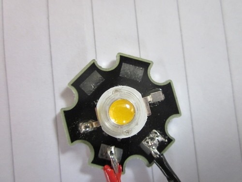
it's a 1W warm white LED on a star board. It requires a current of 360mA and the forward voltage at that current is something like 3.4V. To drive it I'm going to throw together a simple buck converter controlled by PWM from the processor. As the PID loop is going to control the current through the LED, rather than the voltage across it, I'll need a way to measure that current. The simple way to do that is to have a low-value resistor in series with the LED and read the voltage across it with the A/D [the voltage being proportional to the current]. To keep things as simple as possible, and because I don't need great accuracy here, I'm going to try doing this single-ended (look away now if you're a professional engineer) with one end of the resistor at ground (this may not work, but the only way I'll find out is to try it). The 12-bit A/D in the processor gives steps of 3.3V/4096 = 805uV and that equates to 3.22mA per step with a 0.25 ohm resistor. That's reasonable for what I'm trying to do - my enemy is going to be noise and dealing with the ripple, not the resolution.


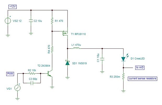
I chose to use 0.25 ohms for the current sense - four 1 ohm resistors in parallel. I always have the option of increasing the value if it doesn't work too well.


Because the current sense is to ground, so is the load, and that means a high-side switch. I've gone for a p-channel MOSFET, though I could have used a transistor. It's a bit messy driving it, with it up in the air like this, but it will do (having a pull-up, rather than an active drive, means that the MOSFET is a bit slow to turn on and off). Because I'm not too worried about efficiency - this isn't a real design that's going to get used for anything - I'm going to use a Schottky diode to catch the coil, rather than try and make it synchronous with a MOSFET to do the job (the Schottky is simple and safe - no possibility of shoot-through destroying the FETs and I won't have to puzzle out how to get two PWM outputs going with a deadband either).


Here's the circuit of the basic converter.


image


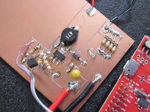
I built it on a piece of pcb material, cutting the lines with a disposable knife (the kind that has a blade with sections that are broken off - the glassfibre blunts the blades very quickly). [Two tips if you decide to try this: 1) don't hurt yourself with the knife - never cut towards yourself because, sooner or later, it will slip and 2) use a continuity tester to prove that the areas are isolated.] The fat traces have low resistance and inductance, so it's not far off what you'd achieve with a pcb in that respect except that there's no ground plane so capacitance to ground is low (which can be a good thing or a bad thing, depending how you look at it).


image


A buck converter like this is stable open-loop, so I powered it up before doing the PID control just to check that it worked and, guess what, it actually lit the LED (excuse me if I sound a bit surprised there). I started with the PWM on the low side and then increased the on period until the voltage across the sense resistors averaged about 90mV [a current through the LED of about 360mA] - I'm basically mimicing slowly what the PID software would do quickly. At this stage I didn't have the capacitor on the output - that way, I could see the full current ripple in the coil without it being partially smoothed (the LED is quite robust and doesn't mind this.)


Here it is with the LED lit up. The paper is to spare my eyesight.


image


I'm working with the PWM set to give me approximately 150kHz. I could go faster, but if I do I'm going to run into problems with the resolution - the period here is 256 intervals of the 25nS that I get with the PWM clock set to 40MHz (it took a lot of fiddling about to get the processor clock to 40MHz because I didn't understand at first how the PLL divisor is set).


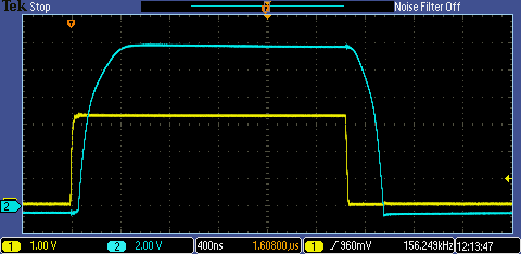
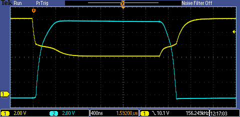
Here are the waveforms of the input PWM (yellow) and the switching node (blue). You can see how the MOSFET is a bit slow to turn on and off. That shouldn't matter at all once it is closed-loop as the software will tune it out. The MOSFET will cope with the extra dissipation - it's not something you'd be proud of in a proper design, but for experimenting with the PID code it will suffice.


image


For interest, here's the gate drive (yellow) against the switching node (blue). I probably should have the divider bringing the gate a bit lower than the 6 volts I went for.


image


Finally, here's the coil current with ripple (blue trace is the sense resistor, yellow is the switching waveform) and a fair amount of noise.


image


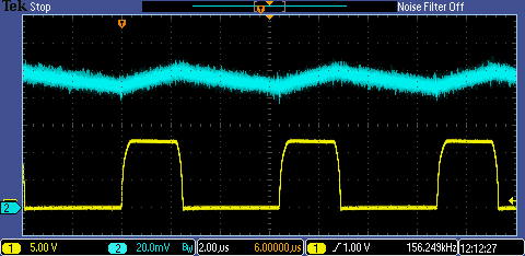
It is what we would expect from a converter like this: when the switch is on, the PSU powers the load through the coil and the current increases, with the magnetic field of the coil storing energy; when the switch is off, the coil drives the switch node negative until the diode conducts, giving it an anchor just below ground, and it then continues to supply the output current which diminishes as energy comes out of the coil's field.


An obvious question that might occur to you here is, if it's stable like this, why bother with the closed-loop control at all?


Three reasons:


1) the input voltage may change
2) I might use a different LED or several LEDs in series
3) the forward voltage of the LED drops as its temperature increases and that increases the current (if the output voltage is fixed) causing more heating resulting in the Vf falling further and so on.


To achieve closed-loop control will require me getting to grips with the PID code, which will be part 3 [this is still work in progress, so don't expect another post for a few days yet ... or a week ... or whatever time it takes me to master it. If I'm not back after a couple of weeks, perhaps send out a search party].

  • Sign in to reply

Top Comments

  • DAB
    DAB over 8 years ago +2
    Nice post and good description of your circuit and test. DAB
  • jc2048
    jc2048 over 8 years ago in reply to michaelkellett

    I was surprised at how clean it all was, too. Shame I no longer have access to any EMC measuring gear or I could see whether it was likely to pass CE (out in the open and on a board without a ground plane).


    I do like that trace of the gate waveform - it shows so well the effect of the gate capacitance as it changes when the channel opens up and closes. A single picture illustrating why driving MOSFETs well at speed is still a bit of an art.


    Good point about the tant. I'm throwing this together from odds and ends, but I probably should be thinking more about the example it sets. (The 10uF capacitor on the circuit diagram is actually a small chip ceramic hiding behind the tant in the photograph - I added the extra tant because I wanted something a bit softer there too.)


    I deliberately set the coil's current ripple a bit on the low side (about 20%). I figured that at this stage it was better to have it a bit sluggish - gives me more of a chance of keeping up with it with the loop.


    I do wonder if I should have presented the design in a bit more detail. It's very difficult to know where to pitch anything like this - explaining how a resistor works and the application of Ohm's law every time gets silly, but there's stuff here I could  have covered better, particularly as it was meant to be illustrative.

    • Cancel
    • Vote Up 0 Vote Down
    • Sign in to reply
    • More
    • Cancel
  • DAB
    DAB over 8 years ago

    Nice post and good description of your circuit and test.


    DAB

    • Cancel
    • Vote Up +2 Vote Down
    • Sign in to reply
    • More
    • Cancel
  • michaelkellett
    michaelkellett over 8 years ago

    The MOSFET waveform isn't that fast but it's nice and clean - so your converter might not be super efficient but it should be quite low noise.


    I wouldn't be that happy about the tantalum bead cap across the input  - at least not for a production design because they are notorious for failing short and catching fire in power supply applications.


    The ripple current is quite low with no output capacitor - this kind of discrete component  switcher is great for understanding how they actually work.


    Good luck with the PID.


    MK

    • Cancel
    • Vote Up 0 Vote Down
    • Sign in to reply
    • More
    • Cancel
element14 Community

element14 is the first online community specifically for engineers. Connect with your peers and get expert answers to your questions.

  • Members
  • Learn
  • Technologies
  • Challenges & Projects
  • Products
  • Store
  • About Us
  • Feedback & Support
  • FAQs
  • Terms of Use
  • Privacy Policy
  • Legal and Copyright Notices
  • Sitemap
  • Cookies

An Avnet Company © 2025 Premier Farnell Limited. All Rights Reserved.

Premier Farnell Ltd, registered in England and Wales (no 00876412), registered office: Farnell House, Forge Lane, Leeds LS12 2NE.

ICP 备案号 10220084.

Follow element14

  • X
  • Facebook
  • linkedin
  • YouTube