


The Hercules LaunchPads of Texas Instruments have two (or three) CAN controllers.
It is possible to learn the CAN protocol and have real messages flowing with the LaunchPad and only three jellybean components.
This series explains how the standard TI examples work, but it goes further than that.
I'll also be looking at the signals with an oscilloscope and logic analyzer.
My first post in this series, Probing your Hercules LaunchPad CAN bus Part 1,
explains the minimal hardware required to get the example working on the LaunchPads (a resistor and two diodes).
In this post I'll check out the example project.
TI's example project
The Hercules examples are available from the HALCoGen Help menu.

You'll find two examples for the CAN controller.
They have the same functionality, but one is interrupt based, the other manages the communication without interrupts.
In my review, I'm using the interrupt driven approach of example_canIntCommunication.

I'm not doing a step by step guide on how to make the example - that's what the help file from HALCoGen is doing.
The focus in this article is on the things that are not documented in HalcoGen Help.
What is that code supposed to do?
The example sends data form the CAN1 of the Hercules microcontroller to CAN2.
Both CAN controllers are activated and configured in HALCoGen. The actual data exchange is coded in C.
Module configuration in HalCoGen
Message box 1 of CAN1 sends messages with ID 1.

Message box 1 of CAN2 listens for messages with ID 1 in its message box 1.
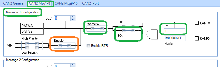
The settings highlighted on the images above show what's happening. In the first picture,
Message box 1 of CAN1 is set up as transmitter, sending messages with ID 1.
You can also see that the interrupt is enabled.
In the second picture, with settings of CAN2 Message box 1, everything is the same, except that this box is configured as receiver.
You can see on the interrupt tabs of HALCoGen what's happening when the interrupts fire.
I've kept all settings as default. The only action in HALCoGen is to enable the channels.
Here's the mapping between the event in the CAN1 tab and the interrupt map:

And this is the mapping for CAN2:

On the VIM tab, you can see how the channels are mapped to interrupt handlers:

If you spend some time in the source files generated by HALCoGen, in particular sys_vim.h, sys_vim.c and can.c,
you can follow how the entries can1HighLevelInterrupt and can2HighLevelInterrupt are resolving to a call to the function canMessageNotification().
The C code in Code Composer Studio:
The program is very small, and we can split it up in 3 sections of only a few lines of C: setup, communication and validation.
The setup
    /* enable irq interrupt in Cortex R4 */
    _enable_interrupt_();


    /** - writing a random data in RAM - to transmit */
    dumpSomeData();


    /** - configuring CAN1 MB1,Msg ID-1 to transmit and CAN2 MB1 to receive */
    canInit();


    /** - enabling error interrupts */
    canEnableErrorNotification(canREG1);
    canEnableErrorNotification(canREG2);
Interrupts are enabled,
test message data is generated (just some data to have a paiload that can be transmitted and received),
the settings from HALCoGen are applied in the canInit() call
and error notification is activated.
communication
    /** - starting transmission */
    for(cnt=0;cnt<D_COUNT;cnt++)
    {
      canTransmit(canREG1, canMESSAGE_BOX1, tx_ptr); /* transmitting 8 different chunks 1 by 1 */
      while(tx_done == 0){};                /* ... wait until transmit request is through        */
      tx_done=0;
      tx_ptr +=8;    /* next chunk ...*/
    }
Thanks to the interrupt support, this piece of code is very condensed. Below is the interrupt handler that completes the whole exchange process:
void canMessageNotification(canBASE_t *node, uint32 messageBox)
{
    /* node 1 - transfer request */
    if(node==canREG1)
    {
      tx_done=1; /* confirm transfer request */
    }


    /* node 2 - receive complete */
    if(node==canREG2)
    {
    while(!canIsRxMessageArrived(canREG2, canMESSAGE_BOX1));
    canGetData(canREG2, canMESSAGE_BOX1, rx_ptr); /* copy to RAM */
    rx_ptr +=8;
    }
}
That's all for the communication part.
validation
    /** - check the received data with the one that was transmitted */
    tx_ptr = &tx_data[0][0];
    rx_ptr = &rx_data[0][0];


    for(cnt=0;cnt<63;cnt++)
     {
          if(*tx_ptr++ != *rx_ptr++)
          {
               error++; /* data error */
          }
     }
This is a simple compare of the data that is sent to the received info.
If error is still 0 after the validation, the data check was ok, and the exact same data that was sent on CAN1 has been received by CAN2.
And that's it. The example isn't that exciting, but a lot of things happened. And you can measure that. In the following post we'll do the setup and measure the real data.
Have a resistor, two diodes and a Hercules LaunchPad ready by then. And boot your scope.

| related posts |
|---|
Top Comments