


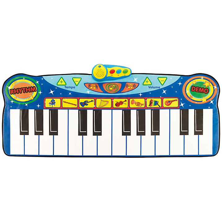
This month I started working on a new project I'm naming Flor(a) piano. I don't know about older generations, but part of my childhood was dancing around on one of these:
The Kit List
You will need the following:
Electronics
Craft materials
- scissors
- black and white material: you need enough of this to back 4 pieces of velostat (front and back)
- material to put the keys on: this needs to cover the size of all 4 keys plus an extra space above the keys to put the flora
- sewing needles
- some form of spray adhesive
Note that the implementation we're building will only create 4 keys - if you want to create a full 12 pitch octave, you will need some extra parts such as digital to analog converters or shmitt converters, as the FLORA only has 4 analog inputs. You will also need to add more velostat and material (2 pieces per white/black key pair)
Step 1: creating the sensor
The first part of this guide is to create the actual keys so we can measure when keys are hit. As a brief explanation, velostat is a good material to use as a cheap step sensor because its resistance changes when it's pressurised - aka, stood on. So velostat will be in the centre of each of our keys.
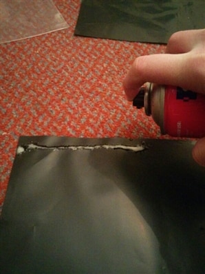
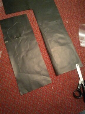
To start this process, we need to glue the sheets together in pairs: we're doing this because the sheets of velostat provided aren't big enough to be floor key sized.
- first, take 1 sheet of velostat. spray a strip of adhesive along one of the shorter sides, and press a second sheet of velostat (again, shorter side) onto the glue strip. It should only be a few centimetres thick.

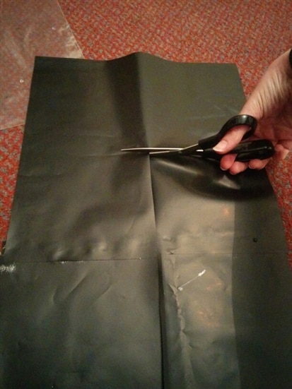
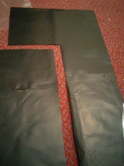
- when the glue's dried, cut vertically down the velostat all the way through the first sheet, and half way through the second, then cut horizontally. You should now have an L shape, which will be a white key, and a smaller section, which will be a black key.
- Cut a piece of white material in the same shape and size as the L shaped piece of velostat you cut. Do the same with the black material for the smaller section.
- Cut a section of conductive thread: make it long enough so that you can stretch from the top of the sensor, to the bottom and round again, with about 10 or so inches left hanging off the top of the sensor.
- Spray glue all over one side of your first sensor. Press the conductive thread down onto this as described above, and then press either white or black material onto it depending which key you're working on
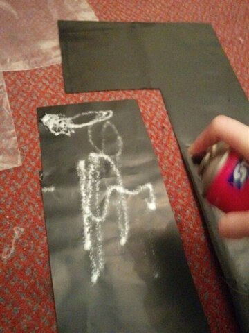
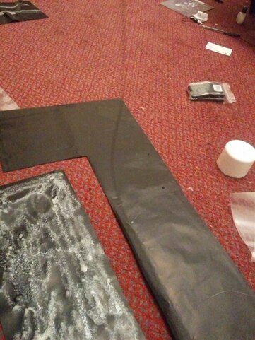

- flip the same sensor over and do the same for that side.
- Do the same 3 steps on the remaining 3 sensors.
Step 2: testing
Before we make things even more permanent, we should probably test the sensors work how we're expecting.
- Take one of your sensors. On each side there should now be a petruding conductive thread - coil up one, and using alligator clips, connect it to GND on the FLORA. Coil up the other and connect it to pin 9 on your FLORA.
- Copy the code from the Github Gist below or clone from my Codebender sketch and load using either the Arduino IDE or the Codebender IDE. I like the latter because it links to my github, works on all platforms without a fuss and I can take my sketches to any other machine.
- Turn your flora on and open up a serial monitor. Among the output you should see a C popping up occasionally, indicating that the sensor's pressure has dropped below a certain level and it thinks it should be playing a C on our piezo buzzer. (We'll put in the buzzer code later on)
Gist:
What do you notice about this code?
Well, firstly, every time you reset the FLORA, the baseline value of what is pressed and what is not pressed will *probably* change, so this means that our simple if statement code isn't very robust.
Secondly, after pressing on the sensor, you should notice there's a period of time where you're not stood on it where the sensor's value rises for a while before getting back to the bottom value.
We'll improve on these bugs later with a better algorithm. For now, test each of your other sensors in turn to make sure they all function as expected - if any don't, you may want to try making a new sensor with sellotape instead of glue and material backing, but hopefully they *will* work ok.
We'll make some improvements on the code in step 3 and finally make the piano a more permanent installation in the next blog post.