element14 Community
element14 Community
    Register Log In
  • Site
  • Search
  • Log In Register
  • Community Hub
    Community Hub
    • What's New on element14
    • Feedback and Support
    • Benefits of Membership
    • Personal Blogs
    • Members Area
    • Achievement Levels
  • Learn
    Learn
    • Ask an Expert
    • eBooks
    • element14 presents
    • Learning Center
    • Tech Spotlight
    • STEM Academy
    • Webinars, Training and Events
    • Learning Groups
  • Technologies
    Technologies
    • 3D Printing
    • FPGA
    • Industrial Automation
    • Internet of Things
    • Power & Energy
    • Sensors
    • Technology Groups
  • Challenges & Projects
    Challenges & Projects
    • Design Challenges
    • element14 presents Projects
    • Project14
    • Arduino Projects
    • Raspberry Pi Projects
    • Project Groups
  • Products
    Products
    • Arduino
    • Avnet & Tria Boards Community
    • Dev Tools
    • Manufacturers
    • Multicomp Pro
    • Product Groups
    • Raspberry Pi
    • RoadTests & Reviews
  • About Us
  • Store
    Store
    • Visit Your Store
    • Choose another store...
      • Europe
      •  Austria (German)
      •  Belgium (Dutch, French)
      •  Bulgaria (Bulgarian)
      •  Czech Republic (Czech)
      •  Denmark (Danish)
      •  Estonia (Estonian)
      •  Finland (Finnish)
      •  France (French)
      •  Germany (German)
      •  Hungary (Hungarian)
      •  Ireland
      •  Israel
      •  Italy (Italian)
      •  Latvia (Latvian)
      •  
      •  Lithuania (Lithuanian)
      •  Netherlands (Dutch)
      •  Norway (Norwegian)
      •  Poland (Polish)
      •  Portugal (Portuguese)
      •  Romania (Romanian)
      •  Russia (Russian)
      •  Slovakia (Slovak)
      •  Slovenia (Slovenian)
      •  Spain (Spanish)
      •  Sweden (Swedish)
      •  Switzerland(German, French)
      •  Turkey (Turkish)
      •  United Kingdom
      • Asia Pacific
      •  Australia
      •  China
      •  Hong Kong
      •  India
      •  Korea (Korean)
      •  Malaysia
      •  New Zealand
      •  Philippines
      •  Singapore
      •  Taiwan
      •  Thailand (Thai)
      • Americas
      •  Brazil (Portuguese)
      •  Canada
      •  Mexico (Spanish)
      •  United States
      Can't find the country/region you're looking for? Visit our export site or find a local distributor.
  • Translate
  • Profile
  • Settings
Personal Blogs
  • Community Hub
  • More
Personal Blogs
Legacy Personal Blogs Putting Probes in Perspective
  • Blog
  • Documents
  • Mentions
  • Sub-Groups
  • Tags
  • More
  • Cancel
  • New
  • Share
  • More
  • Cancel
Group Actions
  • Group RSS
  • More
  • Cancel
Engagement
  • Author Author: caroline_teledynelecroy
  • Date Created: 1 Feb 2019 1:50 PM Date Created
  • Views 820 views
  • Likes 5 likes
  • Comments 0 comments
  • dut
  • probes
  • oscilloscope
  • teledynelecroy
  • differential probe
  • impedance
  • probe
  • teledyne
  • snr
  • lecroy
Related
Recommended

Putting Probes in Perspective

caroline_teledynelecroy
1 Feb 2019

Few aspects of using an oscilloscope are as important as the probe: after all, the probe forms both the mechanical and electrical interfaces between the device under test (DUT) and the oscilloscope itself. To feed a signal into an oscilloscope, we're limited to a coaxial connection. Thus, we need a geometry transformer that picks up the signal of interest from the DUT and transfers it to the oscilloscope's coaxial connection.


image


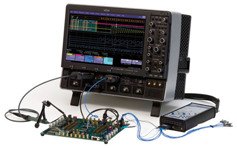
Figure 1: Probe, cable, and oscilloscope form a system that makes or breaks the accuracy of signal acquisitions


That's where the probe comes in as it forms that link between the circuit and oscilloscope. At the same time as it performs that mechanical function, we must depend on our probe to faithfully transfer the signal of interest to the oscilloscope without making a mess of it. To that end, when we consider probes it's best to not limit ourselves to the actual probe itself, but rather to consider the combination of probe, coaxial cable, and oscilloscope as a system (Figure 1).


When thinking about probes, it's also critical to have what we like to call "situational awareness." How is your oscilloscope going to be set up for a given measurement? What features does it bring to the table, and what are its limitations? Most importantly, how do those strengths and limitations match up against the signal of interest and the DUT? We want to be sure that the oscilloscope/probe/cabling system won't contribute to artifacts in the measurement, and that the system's capabilities exceed the requirements for measuring that signal.


There are a few figures of merit (or attributes of merit) with respect to the probing system. For one, as a mechanical interface, it must match the DUT's geometry. It must be mechanically stable in its connections to the signal and return paths. It should introduce minimal discontinuity, and it should not pick up RF interference.


The input impedance to the probe the DUT sees, or the loading the probe imposes on the DUT, is an important attribute. If the probe-system impedance is too low relative to the DUT's impedance, the DUT's output signal(s) will be adversely affected. Bear in mind that the probe-system impedance will typically vary with frequency.


Of course, there's the issue of single-ended vs. differential signals. The former is referenced to local ground, but if signals are differential, you lose common signal information. In many cases, differential measurement can be made using two single-ended probes and calculating the differential and common signal components using the oscilloscope's math functions. This approach will provide both differential and common signal information.


Another important characteristic of the probe-cable-oscilloscope system is its bandwidth, typically defined as the frequency at which its transfer function is -3 dB below its bandpass value (also known as the "half-power" point). This is usually defined based on a fixed source impedance of 50 Ω.


When the DUT output impedance is not 50 Ω, the bandwidth of the measurement system will depend on the DUT's properties.


Finally, there's signal-to-noise ratio (SNR). The oscilloscope's amplifier noise can be on the order of 150 μVRMS. If we are not careful about the probe tip's signal-return geometry, RF pickup noise can be as high as 10-30 mVpk-pk or more. If we're probing volt-level signals, SNR can be as high as 60 dB. But if the signal we're hunting is millivolt-level, the SNR can be much smaller. Improving the SNR means paying attention to the probe-cable-oscilloscope system.


Hopefully, that provides a bit of overall perspective on probes. We'll begin an in-depth look at the classic 10x passive probe in an upcoming post.

  • Sign in to reply
element14 Community

element14 is the first online community specifically for engineers. Connect with your peers and get expert answers to your questions.

  • Members
  • Learn
  • Technologies
  • Challenges & Projects
  • Products
  • Store
  • About Us
  • Feedback & Support
  • FAQs
  • Terms of Use
  • Privacy Policy
  • Legal and Copyright Notices
  • Sitemap
  • Cookies

An Avnet Company © 2025 Premier Farnell Limited. All Rights Reserved.

Premier Farnell Ltd, registered in England and Wales (no 00876412), registered office: Farnell House, Forge Lane, Leeds LS12 2NE.

ICP 备案号 10220084.

Follow element14

  • X
  • Facebook
  • linkedin
  • YouTube