element14 Community
element14 Community
    Register Log In
  • Site
  • Search
  • Log In Register
  • Members
    Members
    • Benefits of Membership
    • Achievement Levels
    • Members Area
    • Personal Blogs
    • Feedback and Support
    • What's New on element14
  • Learn
    Learn
    • Learning Center
    • eBooks
    • STEM Academy
    • Webinars, Training and Events
    • Learning Groups
  • Technologies
    Technologies
    • 3D Printing
    • Experts & Guidance
    • FPGA
    • Industrial Automation
    • Internet of Things
    • Power & Energy
    • Sensors
    • Technology Groups
  • Challenges & Projects
    Challenges & Projects
    • Design Challenges
    • element14 presents
    • Project14
    • Arduino Projects
    • Raspberry Pi Projects
    • Project Groups
  • Products
    Products
    • Arduino
    • Dev Tools
    • Manufacturers
    • Raspberry Pi
    • RoadTests & Reviews
    • Avnet Boards Community
    • Product Groups
  • Store
    Store
    • Visit Your Store
    • 'Choose another store...'
      • Europe
      •  Austria (German)
      •  Belgium (Dutch, French)
      •  Bulgaria (Bulgarian)
      •  Czech Republic (Czech)
      •  Denmark (Danish)
      •  Estonia (Estonian)
      •  Finland (Finnish)
      •  France (French)
      •  Germany (German)
      •  Hungary (Hungarian)
      •  Ireland
      •  Israel
      •  Italy (Italian)
      •  Latvia (Latvian)
      •  
      •  Lithuania (Lithuanian)
      •  Netherlands (Dutch)
      •  Norway (Norwegian)
      •  Poland (Polish)
      •  Portugal (Portuguese)
      •  Romania (Romanian)
      •  Russia (Russian)
      •  Slovakia (Slovak)
      •  Slovenia (Slovenian)
      •  Spain (Spanish)
      •  Sweden (Swedish)
      •  Switzerland(German, French)
      •  Turkey (Turkish)
      •  United Kingdom
      • Asia Pacific
      •  Australia
      •  China
      •  Hong Kong
      •  India
      •  Korea (Korean)
      •  Malaysia
      •  New Zealand
      •  Philippines
      •  Singapore
      •  Taiwan
      •  Thailand (Thai)
      • Americas
      •  Brazil (Portuguese)
      •  Canada
      •  Mexico (Spanish)
      •  United States
      Can't find the country/region you're looking for? Visit our export site or find a local distributor.
  • Translate
  • Profile
Personal Blogs
  • Members
  • More
Personal Blogs
Legacy Personal Blogs PYNQ-Z2 Workshop - Session 1
  • Blog
  • Documents
  • Mentions
  • Sub-Groups
  • Tags
  • More
  • Cancel
  • New
Blog Post Actions
  • Subscribe by email
  • More
  • Cancel
  • Share
  • Subscribe by email
  • More
  • Cancel
Group Actions
  • Group RSS
  • More
  • Cancel
Engagement
  • Author Author: beacon_dave
  • Date Created: 6 May 2020 5:37 PM Date Created
  • Views 518 views
  • Likes 3 likes
  • Comments 3 comments
  • pynq-z2
  • pynq
  • pynqstarter
Related
Recommended

PYNQ-Z2 Workshop - Session 1

beacon_dave
beacon_dave
6 May 2020
image

PYNQ-Z2: Embedded Vision Workshop Series with Adam Taylor


Getting Started | Getting Up and Running  | Unlocking Your Inner PYNQ Hero  | Project14 | PYNQ Workshop image


I recently participated in this Element 14 workshop session https://www.element14.com/community/events/5504/l/pynq-z2-workshop-getting-started-with-pynq-win-a-500-gift-card-for-your-embedded-vision-project led by Adam Taylor, where we took an introductory look at the PYNQ-Z2 development board produced by the Tul Corporation.


In one of the lab exercises we looked at the Logictools overlay and more specifically the Pattern Generator and Trace Analyzer.


The Logictools IP contains four main hardware blocks, namely:

  • Pattern Generator
  • Finite State Machine Generator
  • Boolean Generator
  • Trace Analyzer

which are controlled by a MicroBlaze instance running on the FPGA fabric of the Xilinx ZYNQ XC7Z020 device.

Via the PYNQ framework these blocks can be easily configured via iPython running within a Jupyter Notebook.


The configuration requirement is pretty minimal, most of it is provided by the pre-built PYNQ-Z2 image which just requires downloading and the transfering onto a microSD card and inserting into the PYNQ-Z2 board.


One of the exercises in the PYNQ-Z2 Workshop demonstrated the ease of creating and testing a 3-bit down counter, and here I have modified this to create and test a 4-bit gray-code.


In addition, to installing the PYNQ-Z2 image onto the board, I looped four (of the twenty) Arduino header GPIO outputs (PYNQ-Z2 board has both Arduino and Raspberry Pi headers available) back to four inputs to allow the digital pattern to be generated and then captured and analyzed.


In a real world scenario, these could be connected to an external device allowing the Pattern Generator to be used as a stimulus to control an external circuit, and the Trace Analyzer to monitor it.


The Logictools overlay uses the WaveJSON waveform description format found in WaveDrom  https://wavedrom.com/ and extends it to work with the Pattern Generator to create and render waveforms within the PYNQ framework.


First step is to setup the Logictools overlay and load the bitstream into the FPGA fabric. Then we create the WaveJSON string that defines the waveform to work with, along with the GPIO pins that the waveform will be output to and captured from.


image


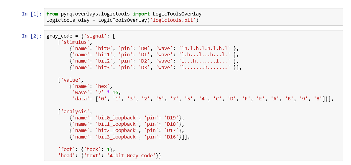
I've added in the hex values for each state for annotation purposes.


Then we can render the waveform in a graphical format which makes it easier to interpret.


image


Note at this stage no analysis data has been captured so the lower half of the diagram contains no data.

We now set up the pattern generator, run it, and render out the results.


image


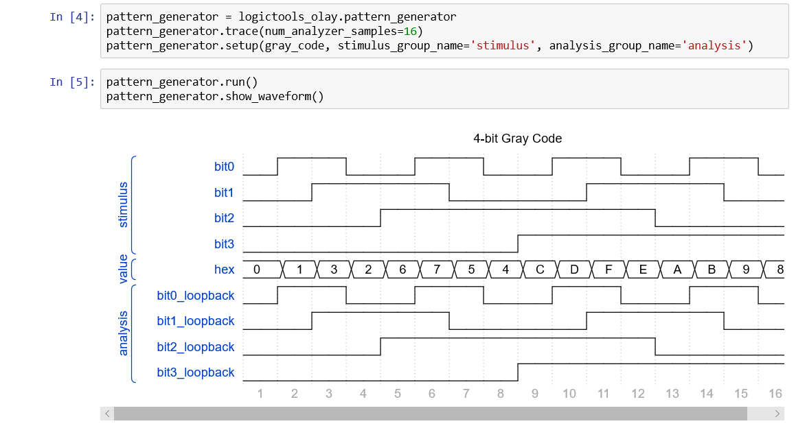
The lower half of the diagram now shows the analysis results captured from the GPIO loopback connection and matches the waveform being generated.


The analysis data can also be displayed in WaveJSON description format if need be...


image


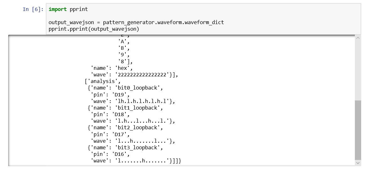
….and can be be further annotated if required.


image

(Interesting to note that the implementation of WaveJSON format on PYNQ doesn't appear to support wave types '6', '7', '8', & '9'.)


This however merely scratches the surface of what can be achieved with the Logictools overlay. Much more background reading and experimentation required !

  • Sign in to reply
  • beacon_dave
    beacon_dave over 3 years ago in reply to Fred27

    ...They're there - over on the right hand side. I think you managed to get a bit out of sync in you binary counting...

    They didn't show up as their correct colours when I tried - I just got type 'x' grey hatches instead.


    image

    (screenshot from https://wavedrom.com/tutorial.html )


    Hence why I just cycled between types 2-5 in the earlier screenshot.

    • Cancel
    • Vote Up 0 Vote Down
    • Sign in to reply
    • More
    • Cancel
  • Fred27
    Fred27 over 3 years ago

    (Interesting to note that the implementation of WaveJSON format on PYNQ doesn't appear to support wave types '6', '7', '8', & '9'.)

    They're there - over on the right hand side. I think you managed to get a bit out of sync in you binary counting.

    • Cancel
    • Vote Up 0 Vote Down
    • Sign in to reply
    • More
    • Cancel
  • DAB
    DAB over 3 years ago

    Thanks for sharing.


    I was interested in the class, but I am just not up to all of the detail anymore.


    DAB

    • Cancel
    • Vote Up 0 Vote Down
    • Sign in to reply
    • More
    • Cancel
element14 Community

element14 is the first online community specifically for engineers. Connect with your peers and get expert answers to your questions.

  • Members
  • Learn
  • Technologies
  • Challenges & Projects
  • Products
  • Store
  • About Us
  • Feedback & Support
  • FAQs
  • Terms of Use
  • Privacy Policy
  • Legal and Copyright Notices
  • Sitemap
  • Cookies

An Avnet Company © 2023 Premier Farnell Limited. All Rights Reserved.

Premier Farnell Ltd, registered in England and Wales (no 00876412), registered office: Farnell House, Forge Lane, Leeds LS12 2NE.

ICP 备案号 10220084.

Follow element14

  • X
  • Facebook
  • linkedin
  • YouTube