element14 Community
element14 Community
    Register Log In
  • Site
  • Search
  • Log In Register
  • Community Hub
    Community Hub
    • What's New on element14
    • Feedback and Support
    • Benefits of Membership
    • Personal Blogs
    • Members Area
    • Achievement Levels
  • Learn
    Learn
    • Ask an Expert
    • eBooks
    • element14 presents
    • Learning Center
    • Tech Spotlight
    • STEM Academy
    • Webinars, Training and Events
    • Learning Groups
  • Technologies
    Technologies
    • 3D Printing
    • FPGA
    • Industrial Automation
    • Internet of Things
    • Power & Energy
    • Sensors
    • Technology Groups
  • Challenges & Projects
    Challenges & Projects
    • Design Challenges
    • element14 presents Projects
    • Project14
    • Arduino Projects
    • Raspberry Pi Projects
    • Project Groups
  • Products
    Products
    • Arduino
    • Avnet Boards Community
    • Dev Tools
    • Manufacturers
    • Multicomp Pro
    • Product Groups
    • Raspberry Pi
    • RoadTests & Reviews
  • Store
    Store
    • Visit Your Store
    • Choose another store...
      • Europe
      •  Austria (German)
      •  Belgium (Dutch, French)
      •  Bulgaria (Bulgarian)
      •  Czech Republic (Czech)
      •  Denmark (Danish)
      •  Estonia (Estonian)
      •  Finland (Finnish)
      •  France (French)
      •  Germany (German)
      •  Hungary (Hungarian)
      •  Ireland
      •  Israel
      •  Italy (Italian)
      •  Latvia (Latvian)
      •  
      •  Lithuania (Lithuanian)
      •  Netherlands (Dutch)
      •  Norway (Norwegian)
      •  Poland (Polish)
      •  Portugal (Portuguese)
      •  Romania (Romanian)
      •  Russia (Russian)
      •  Slovakia (Slovak)
      •  Slovenia (Slovenian)
      •  Spain (Spanish)
      •  Sweden (Swedish)
      •  Switzerland(German, French)
      •  Turkey (Turkish)
      •  United Kingdom
      • Asia Pacific
      •  Australia
      •  China
      •  Hong Kong
      •  India
      •  Korea (Korean)
      •  Malaysia
      •  New Zealand
      •  Philippines
      •  Singapore
      •  Taiwan
      •  Thailand (Thai)
      • Americas
      •  Brazil (Portuguese)
      •  Canada
      •  Mexico (Spanish)
      •  United States
      Can't find the country/region you're looking for? Visit our export site or find a local distributor.
  • Translate
  • Profile
  • Settings
Personal Blogs
  • Community Hub
  • More
Personal Blogs
Legacy Personal Blogs Running the current amplifier without De-coupling capacitors
  • Blog
  • Documents
  • Mentions
  • Sub-Groups
  • Tags
  • More
  • Cancel
  • New
  • Share
  • More
  • Cancel
Group Actions
  • Group RSS
  • More
  • Cancel
Engagement
  • Author Author: three-phase
  • Date Created: 25 Jun 2019 8:31 PM Date Created
  • Views 1390 views
  • Likes 6 likes
  • Comments 9 comments
  • temperature measurement
  • polymer capacitor
  • electrolytic capacitors
  • de-coupling capacitors
  • current amplifier
Related
Recommended

Running the current amplifier without De-coupling capacitors

three-phase
three-phase
25 Jun 2019

This is a little extension of my tests on the current amplifier I have been working on. The amplifier was previously used in the Experimenting with Polymer Capacitors design challenge and during the testing I noticed that the polymer capacitors seemed to be running at a slightly higher temperature in comparison to the electrolytic capacitors I was comparing them to.


A suggestion by jw0752 was to take temperature measurements of the capacitors with them electrically isolated from the amplifier supply circuit, this should then determine if the heat differential was being created from the internal impedance of the capacitors or from the heat radiated from the surrounding components.


As the PCBs are now actually in quite a state, due to the continual de-soldering and soldering of the different capacitors, isolating them from the supply rails was relatively easy. Temperature measurements were therefore successfully carried out and showed the Polymer capacitors still running a little warmer then the electrolytics.


However, with the opportunity of the board in this state, I could not resist running the test measurements and then comparing them to the 220uF Polymer capacitor test results. The table below shows the results of those measurements.


image

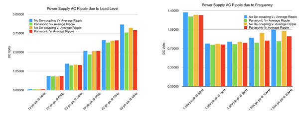
Put into graphic format;


image

The average voltage for both the positive and negative rails is slightly higher without the de-coupling capacitors installed. For the positive rail, both DC fluctuation and AC ripple are significantly lower when the de-coupling capacitor is installed. This would be expected. The same trend is not seen for the negative rail, where only the AC ripple is seen to be lower with a de-coupling capacitor installed.


Looking ore closely at the DC Fluctuation;

image

As the load is increased in the lefthand plot, the fluctuation remains relatively constant up to the 3V input, around 1.8A output. After this the 220uF capacitor starts to have an effect and shows a lower fluctuation level. At 5V input, the negative rail shows the same level of fluctuation with or without the capacitor.


The righthand plot shows the fluctuation as the frequency is increased. The results are a little sporadic, with the fluctuation on the negative rail generally lowest without a de-coupling capacitor installed. At the highest frequency of 20kHz, the fluctuation is reduced with the 220uF capacitor installed, but this is the only result that really matches expectations.


The same set of test are then completed whilst measuring AC ripple.

image

The effects on load change are not as apparent as they were for the DC fluctuation, with the majority of the readings similar with or without a capacitor installed. At the highest load, about 3A output, the 220uF capacitor is starting to have an effect, more on the positive rail than the negative.


The plot for the frequency changes, shows better performance with a 220uF capacitor installed at the 10kHz and 20kHz frequencies, with no real differences seen at the lower frequencies.


image

Comparing the gain of the amplifier, it can be seen that a slightly lower average gain is seen when a de-coupling capacitor is installed. However, there is much less deviation in gain across the range of tests, when the capacitor is installed. The minimum gain seen is the same for both sets of tests and in actual fact the same 4V Input tests shows the lowest gain of 1.965 with or without a capacitor. With a capacitor installed, the maximum gain only ever reaches 2.020 for the 2V input test, which is different when no de-coupling capacitor is fitted than has the highest gain of 2.068 at the 5V input test, which represents the maximum load on the amplifier.


A further set of temperature measurements has been carried out to cater for the different current output on the amplifier. I run these tests with both amplifier boards in operation, one with the polymer capacitors in and the other with the electrolytics. The load resistors measure 1.004275 Ohms and 1.001264 Ohms, but one amplifier always puts out about 2.50A and the other 2.35A. This means that the amplifier runs slightly cooler on one board. I can only attribute the difference, to slightly different gain in the two amplifiers as swapping over the load resistors makes little difference.


In the first set of tests, the polymer capacitors were installed in the board operating at lower load but they operated about 4 Deg C higher than the electrolytic capacitors. For some reason, I didn't think to swap the capacitors over between the two boards to verify if the temperature went up, but I have now done this to provide a little extra data.


The picture on the left shows the original temperature measurements, the picture on the right, is with the capacitors swapped over between the boards. The table below summarises the results.


imageimage

image

It can be seen that for both boards, the polymer capacitors run at a higher temperature than the electrolytics, irrespective of the amplifier temperature. It should also be remembered that the test boards are open to the air, mounted inside a case, the temperature differentials would likely be even higher. Having said that, they aren't at a level that are beyond the specification of the capacitors.


I still am not too happy with the performance of the thermal imaging camera. You can see in both pictures, that the spot temperature on the amplifier is actually higher than the scale to the side of the picture. I am not sure what the cause of this is. There are different the of surfaces on the components and to be technically correct, the emissivity of them will be different, which could cause slight in accuracies, but I am not sure that this is why the scale would be recorded as lower.


If I can find some way to attach thermocouples to the relevant devices, and find enough thermocouples, I may look to make a comparative measurement using a different methodology. It would also be an ideal test for the DAQ970A, that I have been luck enough to be selected to roadtest.

  • Sign in to reply

Top Comments

  • jw0752
    jw0752 over 6 years ago +4
    Hi Donald, Great follow up experiment. As is usually the case an attempt to solve a mystery results in more mysteries. Fortunately we do approach the truth and learn new things in the process. John
  • three-phase
    three-phase over 6 years ago in reply to jw0752 +4
    Many thanks John. There is some consistency with some of the results, but I suspect that the combination of the unregulated supply and the design of the amplifier are accounting for a lot of the sporadic…
  • jw0752
    jw0752 over 6 years ago in reply to three-phase +2
    In case you want some more experiments I can think of a couple more variations. John
  • three-phase
    three-phase over 6 years ago in reply to three-phase

    I have taken a couple of snapshots with the thermal camera with a polymer and electrolytic capacitor hooked up to a DC supply of about 9V. The first picture is a at more of angle to the capacitors and the temperatures come out at around 15 Deg C.


    image

    The second picture I took right above the capacitors and the temperature comes out 5 degrees higher.


    image

    On both occasions, the polymer and electrolytic are around the same temperature. The second picture is closer to the ambient temperatures at the time.


    I also plotted the current of reach capacitor from initial switch on to 90 seconds after.


    image

    You can see the electrolytic settles to a much lower current than the polymer capacitor, dropping below 1uA where as the polymer dropped down to about 8uA.


    Kind regards.

    • Cancel
    • Vote Up +2 Vote Down
    • Sign in to reply
    • More
    • Cancel
  • three-phase
    three-phase over 6 years ago in reply to jw0752

    Ahh perfect, I understand now, I should be able to get to work on that and produce some results over the next few days. I can run them in parallel, but may be a good idea to test them individually as well, to ensure that there are no circulating currents between them that would affect the results. Not sure if that would be the case or not?


    Kind regards.

    • Cancel
    • Vote Up +2 Vote Down
    • Sign in to reply
    • More
    • Cancel
  • jw0752
    jw0752 over 6 years ago in reply to three-phase

    Hi Donald,


    Now we have a baseline and know that the capacitors give basically equal readings to the thermal camera. Here is my idea for the second part of the experiment:


    image


    By applying the power to each type of capacitor equally in this environment isolated from the amplifier we can hopefully see the effect of just the power and the way the capacitor reacts to it. By supplying the rails from each side like this we give each capacitor the same potential.


    John

    • Cancel
    • Vote Up +2 Vote Down
    • Sign in to reply
    • More
    • Cancel
  • three-phase
    three-phase over 6 years ago in reply to jw0752

    Hello John,


    First one is an easy one to do.


    image

    I took a few measurements and sometimes I could get a couple of degrees difference between both sets, with the electrolytic being cooler. However, all of the components would read the same temperature, so the capacitors, amplifier and heat sink were all a couple of degrees cooler. Not sure what was causing that, I can only think it was the position of the camera and how close it was to the board.


    Whilst the electrolytic has a covering around the sides, the top of the can is open and I presume to be the same material as the polymer capacitor can. However, several spot temperature points around the various components, all record very close temperature readings.


    The pictures are in photo format, as when there is no temperature differential, the thermal image is just a wash out.


    image


    For the second one, I presume you mean for me to reconnect the capacitors, and re-run the test with power on, but no load on the amplifier? I should be able to get this done over the weekend.


    Kind regards.

    • Cancel
    • Vote Up +1 Vote Down
    • Sign in to reply
    • More
    • Cancel
  • jw0752
    jw0752 over 6 years ago in reply to three-phase

    Hi Donald,


    The two questions that I currently have are:


    When isolated, at room temperature, and no voltage applied, do you get the same temperature reading on the two different caps using the IR thermometer? I am wondering if the IF thermometer might read the two different materials on the caps differently even if they are at the same temp.


    And


    If the two different caps are isolated from the amp with the same unfiltered DC voltage applied, is there a measurable difference in temperature? Here I am wondering if the ESR will produce a readable temperature difference.


    This is just curiosity and I don't mean to make any work for you so don't run the experiments unless they make sense to you. I can tell you are a much better researcher than I am.


    John

    • Cancel
    • Vote Up +1 Vote Down
    • Sign in to reply
    • More
    • Cancel
>
element14 Community

element14 is the first online community specifically for engineers. Connect with your peers and get expert answers to your questions.

  • Members
  • Learn
  • Technologies
  • Challenges & Projects
  • Products
  • Store
  • About Us
  • Feedback & Support
  • FAQs
  • Terms of Use
  • Privacy Policy
  • Legal and Copyright Notices
  • Sitemap
  • Cookies

An Avnet Company © 2025 Premier Farnell Limited. All Rights Reserved.

Premier Farnell Ltd, registered in England and Wales (no 00876412), registered office: Farnell House, Forge Lane, Leeds LS12 2NE.

ICP 备案号 10220084.

Follow element14

  • X
  • Facebook
  • linkedin
  • YouTube